By Frédéric Jacques – Application Specialist – SolidXperts
Do you want to avoid designing sheet metal parts beyond the dimensional limits available? Add an alert (sensor) to your SOLIDWORKS model.
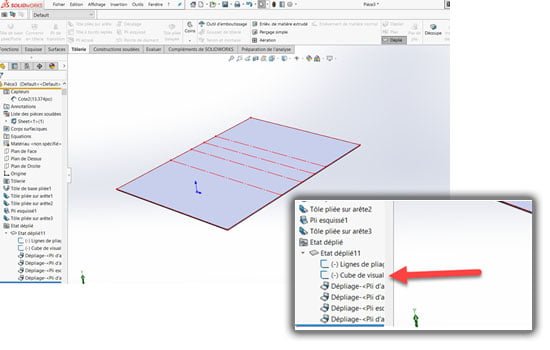
Step 1: Display the View Orientation Cube
Display the flattening of your sheet metal part. Make sure the sketch of the viewing cube is not in hidden mode.
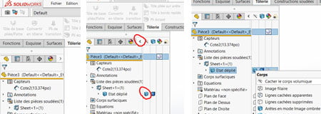
 Step 2: Hide the Volume Body
Hide the solid body to show only the fold lines and the viewing cube of the unfolded part. To do so, unfold the display status bar in the creation tree (Feature Manager). Right-click on the body displayed in the open tab and select hide volume body.
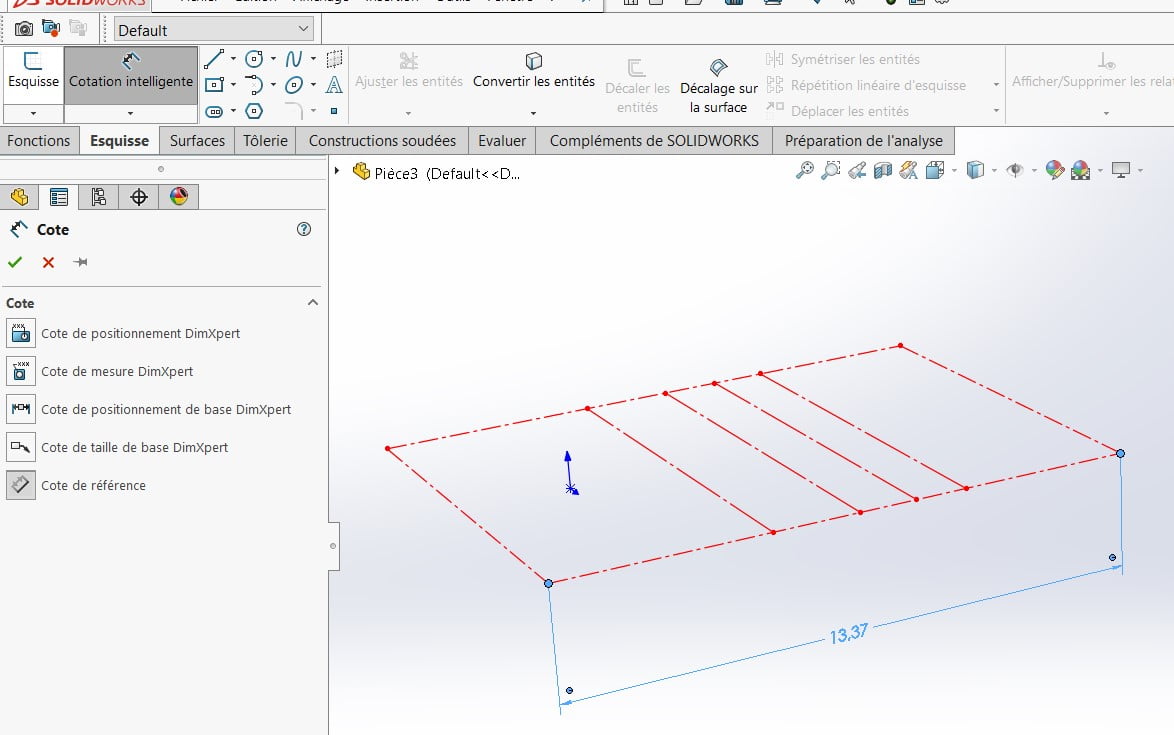
 Step 3: Place a Reference Dimension
 Step 3: Place a Reference Dimension
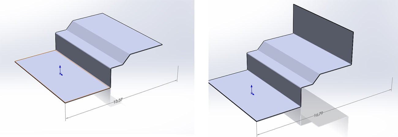
Now you can see the sketch of the viewing cube automatically created by a sheet metal part in SOLIDWORKS. This represents the overall volume of the part and you can place a reference dimension on the length, width, or thickness. Be careful not to select sketches that represent bend lines.
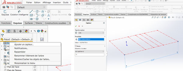
 Step 4: Create a Dimension Sensor
 Step 4: Create a Dimension Sensor
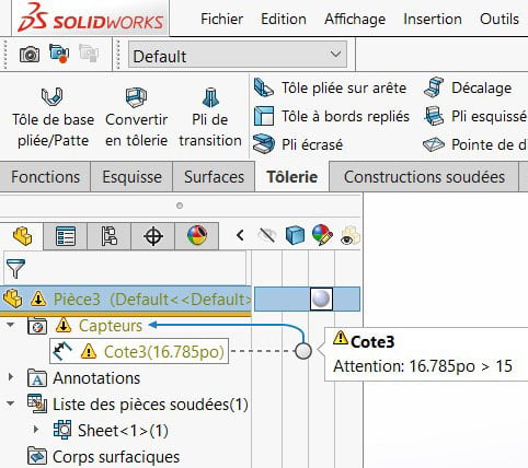
Include a sensor. Right-click on the sensor icon in the creation tree and select “Add a sensor”. Select a dimension sensor and submit the desired conditions.
Sensor type = Dimension
Properties = Select the reference dimension that has been added (13.37″)
Alert = Check the box “Warn me if the value = …”
Select “is greater than” and write the value not to be exceeded. (15″ in the example)
 Step 5: Check Sensor Operation
 Step 5: Check Sensor Operation
Finally, display the volume body again, and apply any modifications to your part in the folded state. A warning message is then displayed in the shaft if you are no longer within the defined values of the sensor.
SolidXperts teams can help you become true 3D experts! An additional question? Need information?
Contact us!
SolidXperts team is always there for you!


