Introduction
Large-scale 3D printing is revolutionizing the manufacturing industry, offering the ability to create objects of incredible size and complexity. From prototypes to producing end-use parts, large-scale 3D printing opens a world of possibilities, but with this exciting technology comes a host of questions, many of which you may not even know you had.
In this blog, we will explore 20 essential questions about large format 3D printers, providing you with the answers you need to understand this innovative technology. We’ll delve into the capabilities of large format 3D printers, the industries that benefit the most, the materials that can be used, the sustainability aspect, the limitations, the cost-effectiveness, and much more.
1. What Is Large-Scale 3D Printing and How Does It Differ from Standard 3D Printing?
Large-scale 3D printing creates massive 3D printed objects using specialized technology with larger build volumes and extruders. It enables the production of large, intricate objects in one piece, offering new possibilities for industries like architecture, automotive, and aerospace.
2. What Are the Capabilities of a Large Format 3D Printer?
Large-format 3D printers offer a range of capabilities that make them ideal for a variety of applications. Here are some key capabilities of large-scale 3D printers:
- Build volume: As you might expect, large format 3D printers have significantly larger build volumes compared to standard 3D printers, allowing for the creation of large objects in a single print.
- Print quality: Despite the larger size, large-scale 3D printers can produce high-quality prints with intricate details and smooth surfaces.
- Large objects: With their spacious build platforms, large-scale 3D printers can create objects that would be impossible to produce with standard printers.
- Speed: Large-scale 3D printers can produce objects at a faster rate, reducing production time and increasing efficiency.
These capabilities make large-scale 3D printers a valuable tool for industries such as prototyping, manufacturing, and product development.
3. Which Industries Benefit Most from Large Format 3D Printers?
Large-scale 3D printing benefits various industries, especially prototyping and large format manufacturing. It saves time and money in product development by enabling quick production of prototypes. In manufacturing, it creates large objects in a single piece, cutting down on assembly time. Industries like construction, automotive, aerospace, and architecture can streamline production processes and bring innovative products to market faster with large-scale 3D printing.
4. What Filaments Can Be Used in Large-Scale 3D Printing?
Large-scale 3D printing offers a wide range of material options. Just like standard 3D printers, large-scale printers can use various types of filaments, including PLA, ABS, PETG, nylon, and more. These filaments come in different colors and properties, allowing for versatility in printing applications.
Additionally, large-scale 3D printers often come equipped with specialized extruders that can handle larger filament sizes. This opens the possibility of using materials such as carbon fiber composites, metal-filled filaments, and other high-performance materials.
With the ability to use a wide range of materials, large-scale 3D printing offers flexibility and the opportunity to create objects with specific properties, such as strength, heat resistance, and conductivity.
5. Can Large-scale 3D Printing Be Sustainable and Eco-Friendly?
Large-scale 3D printing can be sustainable by minimizing waste through additive manufacturing techniques. It uses only necessary materials, reducing waste. Additionally, it can utilize recycled and biodegradable materials, further reducing environmental impact. Advanced features like filament detection and automatic bed leveling ensure efficient and precise printing, minimizing reprints and waste.
As 3D printing evolves, the industry seeks to make it even more sustainable, offering a greener alternative to traditional manufacturing methods.
6. What Are the Limitations of Large-Scale 3D Printing?
Large-scale 3D printing has advantages but also limitations. Surface finish can have visible layer lines due to the printing process, but post-processing techniques like sanding or painting can improve it.
Size constraints do exist for large objects, which may require printing in parts and assembling later. Costs of printers and materials can be limiting, but as technology advances, costs are expected to decrease, expanding accessibility to various industries.
7. How Cost-Effective Is Large-scale 3D Printing Compared to Traditional Manufacturing?
Large-scale 3D printing offers cost-effective advantages over traditional manufacturing. It reduces assembly and labor time as well as material costs. It even enables rapid prototyping.
Consider design complexity, object size, and material when evaluating cost-effectiveness.
8. How Do You Choose the Right Large-scale 3D Printer for Your Project?
Choosing the right large-scale 3D printer for your project requires careful consideration of several factors. Here are some key considerations to keep in mind:
- Print quality: Assess the print quality of the printer by examining sample prints or researching customer reviews. Look for printers that consistently produce high-quality prints with good accuracy and detail.
- Large format capabilities: Determine the maximum build volume of the printer and ensure it meets your requirements for the size of objects you intend to print.
- Features and functionalities: Consider additional features such as automatic bed leveling, filament detection, and print resume after power loss. These features can enhance the printing experience and minimize the risk of failed prints.
- Support and warranty: Look for manufacturers that offer reliable customer support and a warranty on their printers. This will ensure that you have assistance in case of any issues or technical difficulties.
9. How do you Prepare Designs for Large-scale 3D Printing and Prototyping?
Preparing designs for large-scale 3D printing requires careful consideration of factors such as size, support structures, and print orientation.
- Size considerations: Ensure that your design fits within the maximum build volume of the printer. If the object is too large, it may need to be printed in multiple parts and assembled later.
- Support structures: Determine if your design requires support structures to ensure successful printing. Large overhangs or intricate details may require support structures to prevent sagging or collapsing during the printing process.
- Print orientation: Consider the best orientation for your design to minimize the need for support structures and achieve the desired strength and surface finish.
- File format: Save your design files in a format compatible with the large-scale 3D printer’s software, such as STL or OBJ.
10. How Fast Can Large-scale 3D Printers Produce Objects?
Large-scale 3D printers’ print speed varies based on design complexity, object size, and print settings. They generally outpace standard printers due to their larger volumes and specialized extruders. However, intricate or bigger objects may take longer. Print quality and resolution preferences can also impact speed.
Optimize by selecting suitable settings like layer height and speed and maintaining printer calibration.
11. How Does Large-scale 3D Printing Facilitate Customization?
Large-scale 3D printing allows for unmatched customization capabilities, enabling businesses and individuals to tailor designs to specific requirements. From unique architectural structures to personalized automotive parts and individualized prototypes, large-scale 3D printing offers a new level of customization. This can enhance customer satisfaction, product functionality, and brand differentiation.
By leveraging large-scale 3D printing, businesses can provide tailored solutions that meet client needs and stand out in the market.
12. What Types of Support Structures Are Needed for Large-scale 3D Printing?
Support structures are crucial in large-scale 3D printing, especially for complex designs or objects with overhangs. They provide temporary support, preventing sagging or collapsing. The type of support required varies based on the object’s design and print orientation. Common types include tree-like, lattice, and solid structures. Adjusting placement and density can optimize material usage and reduce post-processing. Careful consideration of support structures is vital for successful large-scale 3D prints.
13. Can Large-scale 3D Printing Be Used for Building Construction?
Large-scale 3D printing can revolutionize construction by enabling the printing of large, complex parts efficiently. It allows for custom-designed components, enhancing architectural flexibility and sustainability. Successful projects worldwide have demonstrated its potential in building houses, offices, and villages. As the technology progresses, expect more innovative applications in the construction industry.
14. What Safety Measures Should Be Considered in Large-scale 3D Printing?
Safety is vital in large-scale 3D printing. Proper ventilation is crucial to minimize exposure to harmful fumes. Operating the printer correctly, following guidelines, and regular maintenance are key safety measures. Fire safety measures like fire extinguishers and smoke detectors are essential due to the heat generated by these printers.
By implementing these safety measures and following best practices, large-scale 3D printing can be done safely and effectively.
15. What is the Typical Accuracy of Large-Scale 3D Printers?
The accuracy of large-scale 3D printers can vary depending on various factors such as the printer’s design, print settings, and the complexity of the object being printed. However, in general, large-scale 3D printers offer a high level of accuracy, allowing for precise and detailed prints.
16. How Does the Resolution of a Large-Scale 3D Printer Compare to Smaller Printers?
Large-scale 3D printers typically have a comparable resolution to smaller printers. However, due to their larger build volume, the resolution may appear slightly lower when printing large objects. Nonetheless, large-scale printers can still achieve impressive levels of detail and quality.
17. What Maintenance Is Required for Large-scale 3D Printers?
Like any 3D printer, large-scale printers require regular maintenance to ensure optimal performance. This includes tasks such as cleaning the print bed, calibrating the printer, and replacing worn-out parts.
Following the manufacturer’s guidelines and performing routine maintenance will help prolong the lifespan of the printer and ensure consistent print quality.
18. Can Large-scale 3D Printing Be Done with Metals?
Yes, large-scale 3D printing can be done with metals. Metal 3D printing, also known as additive manufacturing, is a rapidly growing field that allows for the creation of complex metal objects.
With advancements in technology, large-scale metal printing is becoming more accessible and offers exciting possibilities in industries such as aerospace, automotive, and healthcare.
19. How Do Environmental Conditions Affect Large-scale 3D Printing?
Environmental conditions can have an impact on large-scale 3D printing. Factors such as temperature, humidity, and airflow can affect the print quality and overall success of a print. It is important to ensure that the printing environment is controlled and optimized for best results. This may include using an enclosed printer or implementing measures to regulate temperature and humidity.
20. Can Large-scale 3D Printed Items Be Recycled?
Yes, large-scale 3D printed items can be recycled depending on material. Many 3D printing materials, such as PLA and ABS, are recyclable. However, it is important to note that the recycling process for large-scale prints may differ from smaller prints due to their size. Recycling options may include shredding the prints into smaller pieces or using specialized recycling facilities.
Builder 3D Printers – Large Format Printing Made Easy
Builder 3D printers are at the forefront of large-scale 3D printing technology. Designed and produced in the Netherlands, these printers offer a range of features and capabilities that make large-format printing easy and accessible.
One of the standout features of Builder 3D printers is their large build size. With a build capacity over 1 x 1 meter, these printers can handle printing large and complex objects in one piece, making them ideal for projects with a high print volume. This opens new possibilities for creating large prototypes, tools, and even parts for building construction.
In addition to their impressive build size, Builder 3D printers also come with features such as automatic bed leveling and filament detection. These features ensure accurate and reliable printing, minimizing the risk of failed prints and saving valuable time and resources.
Whether you’re a business looking to streamline your prototyping process or an individual maker with ambitious projects in mind, Builder 3D printers offer the perfect solution for large-format printing needs.
Features of Builder 3D Printers
Builder large format printers are equipped with a range of features that make them stand out in the world of large-scale 3D printing. These features ensure high-quality prints and user-friendly operation, making them the go-to choice for many professionals and enthusiasts. Here are some key features of Builder large format printers:
These features, combined with the reliability and precision of Builder printers, make them a top choice for large-scale 3D printing projects.
| Feature |
|
| Large Build Size |
Builder printers offer a generous build volume, allowing for the creation of large-scale objects. |
| Automatic Bed Leveling |
This feature ensures that the print bed is perfectly leveled, resulting in accurate and consistent prints. |
| Filament Detection |
Builder printers are equipped with filament detection sensors that alert users when filament runs out or breaks, preventing failed prints. |
| Easy Access to Build Plate |
The design of Builder printers allows for easy access to the build plate, making print setup and removal hassle-free. |
| Multiple Nozzle Diameters |
Builder printers come with various nozzle diameters, allowing users to choose the optimal size for their specific printing needs. |
These features, combined with the reliability and precision of Builder printers, make them a top choice for large-scale 3D printing projects.
Conclusion
Large-scale 3D printing opens a world of possibilities, revolutionizing industries and manufacturing processes. From materials to sustainability, this technology offers innovation at its core. Understanding its capabilities, limitations, and benefits is crucial for choosing the right printer for your project. Customization, speed, and accuracy are key factors shaping the future of large-scale printing. Embrace this cutting-edge technology with informed decisions and unleash your creativity like never before. Dive into the realm of large-scale 3D printing and witness the transformative power it holds for the future of manufacturing and design.


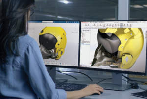
 3D Creator Streamlines Your Design Workflow


