The sheet-metal module included in SolidWorks allows us to create different types of consumer products that are part of our daily lives.
These products can be broken down into standard parts for mass production. One of the quickest ways to create a sheet-metal assembly is to use the function Convert to Sheet Metal from a Prismatic Volume’. This method is best suited for standard, non-thin geometries. However, we can also use it with thin-walled geometries.
Let’s take this kitchen hood as an example. Let’s see how to create this in SolidWorks using the Convert to Sheet Metal command. First, we create a prismatic volume with standard modeling techniques. We then separate the geometry into different sheet-metal bodies. We make sure the overall width and length of each body can fit on the raw material that we will use for manufacturing. Finally, each sheet metal body will be assembled together by the welding or bolting process. The challenge while using this technique is to keep the welding gaps as small as possible.
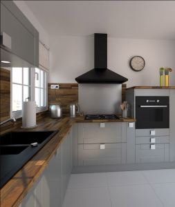
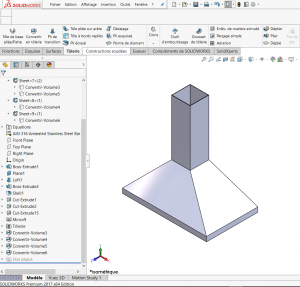
Step 1, Create the kitchen hood with standard modeling techniques (Extrusion, Loft, Extrude Cut, Shell etc…)
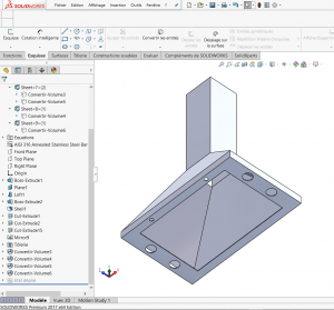
We have created a cut-out in the base to receive the lights and filters.
Step 2, Create Rip Sketch.
We will create a 3D sketch of each joint. This sketch will create the Rip feature along the joint at each side of the hood. Multiple sketches or one single-contour sketch can be used to create multiple rips.
Now, we can use ![]() Convert to sheet metal in the command panel or use the drop-down menu insertion/sheet metal/convert to sheet metal to create the fourth sheet metal solid bodies.
Convert to sheet metal in the command panel or use the drop-down menu insertion/sheet metal/convert to sheet metal to create the fourth sheet metal solid bodies.
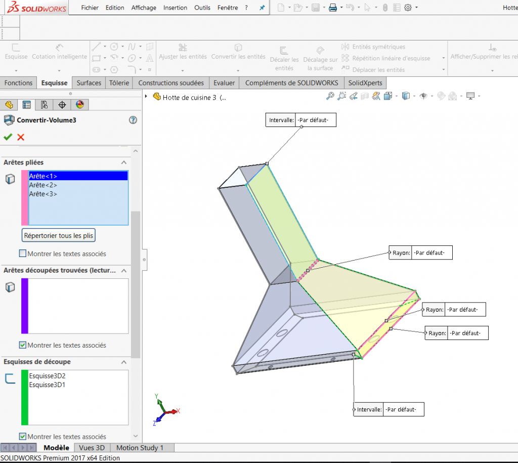
Step 3, Create the first sheet metal body.
In the property manager, you need to specify:
- A fixed face,
- Sheet thickness
- Bend Edges (radius default)
- 3D sketches as the rip sketch, 2 per body (gap default)
- Default gaps for all rips
- Auto Relief.
To be able to keep the original volume, you need to check the keep body option.
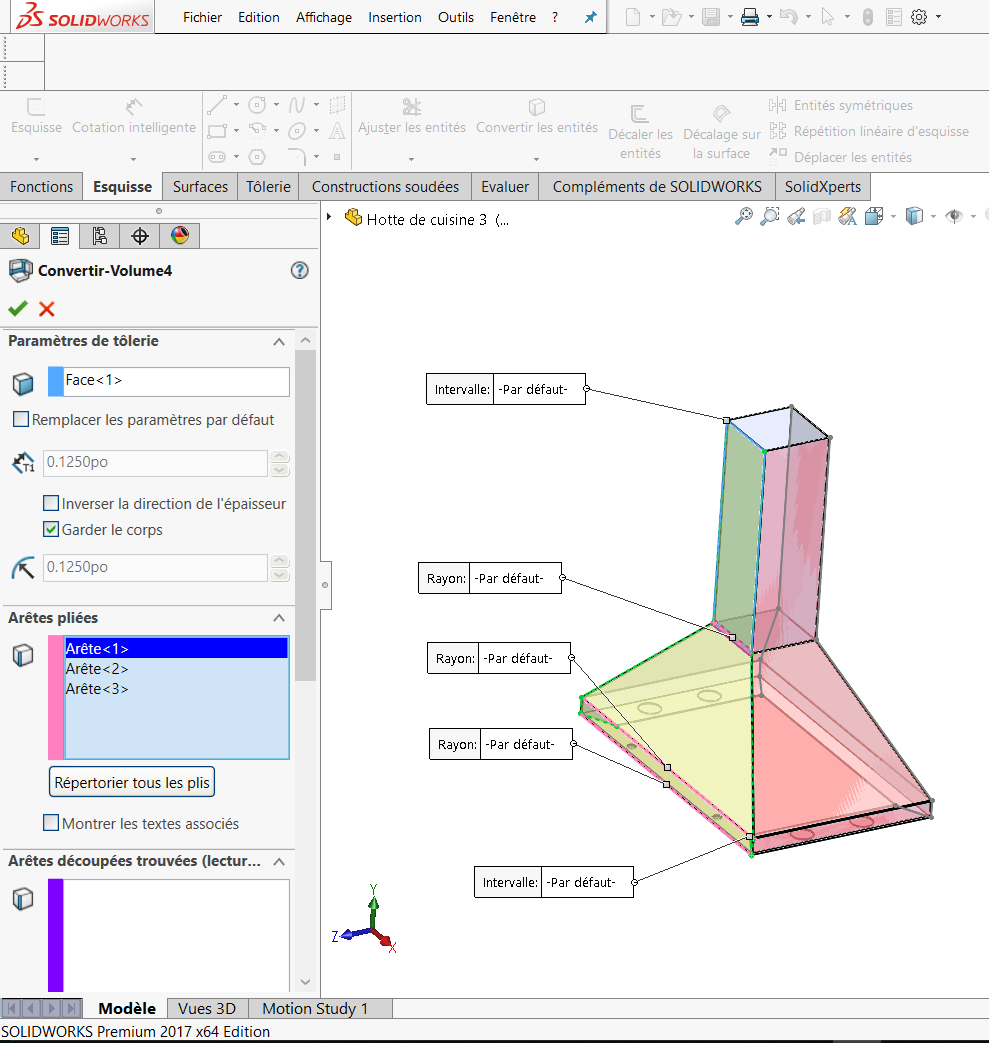
Step 4, Creating the second sheet metal body.
Since we have checked the Keep Body option, the prismatic volume is again available to select the parameter for the second sheet-metal body. The red faces below indicate the location of the first sheet-metal body.
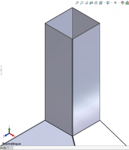
Step 5, Creating the third and fourth sheet metal bodies.
Follow the same procedure as described above. As a rule, 2x the thickness value can be applied for the dimension of the gaps to avoid interference between the joints.
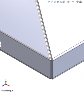
Conclusion
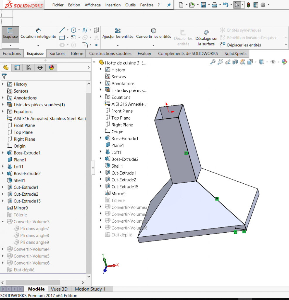
The results of these steps are shown below.
As you can see, the 4 sheet-metal bodies are perfectly joined in the corners. This join is because we have created each body from the same prismatic volume. Another advantage of this technique is that if we change the dimensions of the original volume, all the sheet-metal bodies will update automatically. Each sheet-metal body is saved inside a single file. If you want to export them, you can use the Save as New Part function. This function will create child parts from the original in separate files. To check interference, you can also insert this part into an assembly file and detect interference by checking the option to include multi-body interference.
Marco Chery,
Spécialiste d’application, SolidXperts Inc.
With 25 years of experience and more than 250 certifications, SolidXperts teams can help you become true 3D experts! An additional question? Need information?
SolidXperts team is always there for you!


