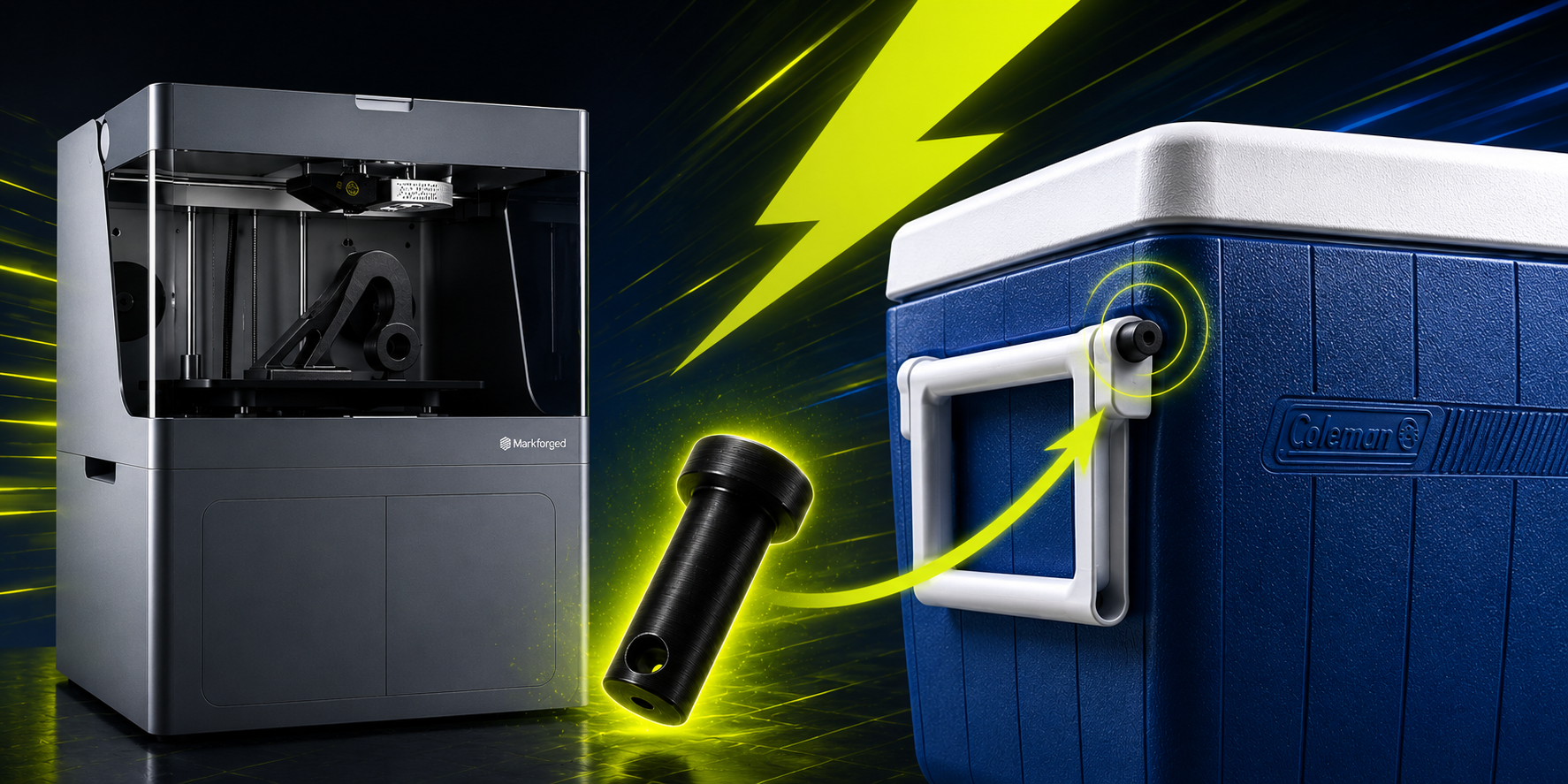
Can you already smell the BBQ?
Last summer, I went to a store to buy a cooler. I found one at an unbeatable price, but it was missing two retaining pins for the handle.
That’s when I had an idea.
Why not design and 3D print them?
So, I left the store with the cooler, a big smile on my face, and full confidence that I could find a solution in time for the BBQ.

Challenge: A Cooler with Missing Parts
A BBQ was scheduled just a few days later. I wanted to buy a cooler to keep drinks cold throughout the evening, but my budget was limited.
I came across a brand-new 45.4 L cooler for the modest price of $15 CAD. The only issue was that it was missing the two pins that secured the handle on one side. Despite searching throughout the store, I was unable to find replacement parts that could be purchased with it.
Without these pins, the cooler was still usable, but moving it around would have been much less convenient since the handle would not function properly. A comparable new cooler would have cost approximately $50 CAD before taxes. Ordering replacement parts was also an option, but not necessarily the most cost-effective one due to potential shipping costs and delivery delays.
With a BBQ quickly approaching, I needed a solution that was both effective and fast.
Evaluating the Options
Let’s take a quick look at the available options:
-
Purchase a New Cooler : The simplest solution, but also the most expensive unless a significant discount is available.
-
Order the Missing Parts : A viable option, but the total cost could quickly increase due to part pricing, shipping fees, and delivery times.
-
Manufacture the Parts In-House : An ideal solution for a company that has access to a 3D printer and the expertise needed to quickly design replacement parts.
Considering the tight timeline, the very low production cost, and the minimal effort required to design and print the parts, I chose additive manufacturing.
Markforged printers can produce durable parts using materials such as onyx, nylon, carbon fiber, fiberglass, and even metal. This makes them an excellent solution for challenges like this one.
Designing and Printing the Pins
I brought the cooler to my colleague, Charles-Olivier Provost, and in less than two hours, the problem was solved.
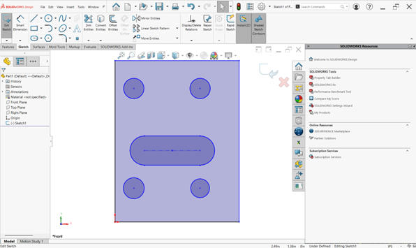
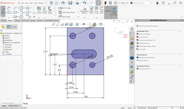
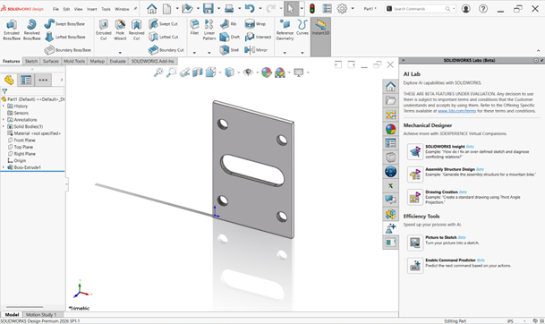
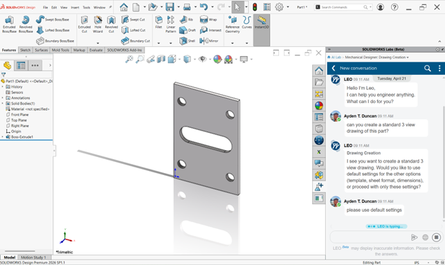
The process was straightforward. He removed one of the existing pins from the functional side of the handle and measured its dimensions using calipers, including diameter, length, and other key features. Using those measurements, he recreated the part in SOLIDWORKS. The modeling process took only a few minutes.
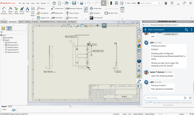
Once the model was completed, it was exported to Markforged’s Eiger software to prepare it for printing.
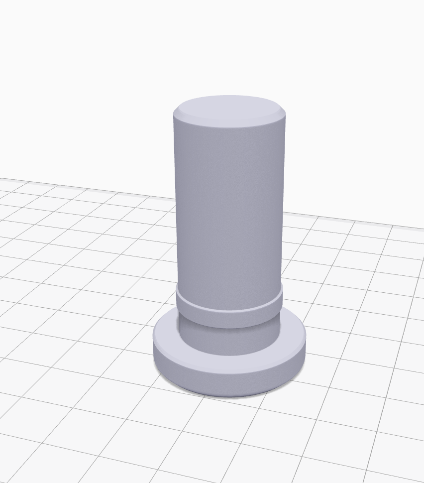
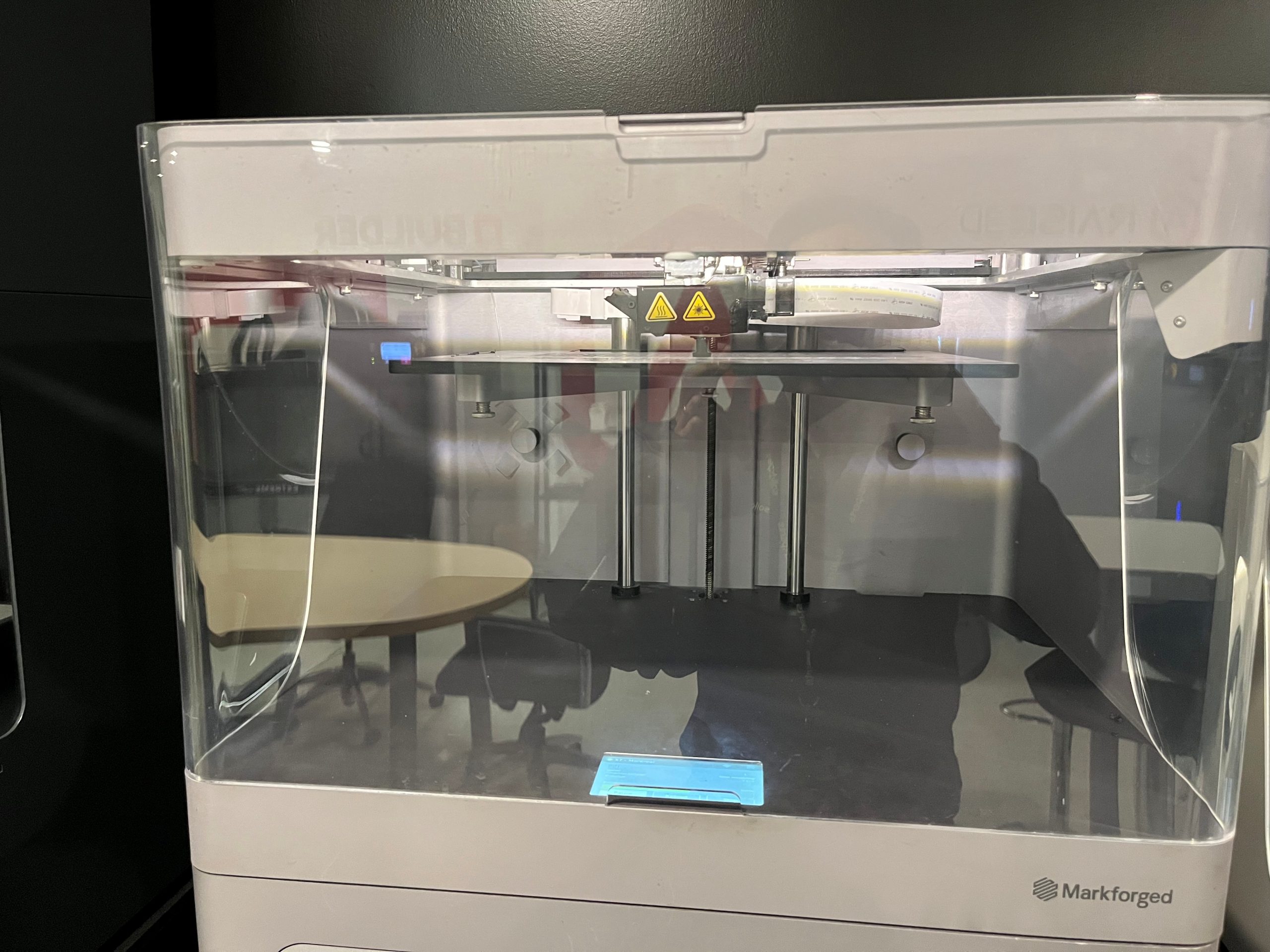
A few minutes later, the print job was launched on a Markforged X7 printer using an onyx material. In just over an hour, the two replacement parts were ready.
Results
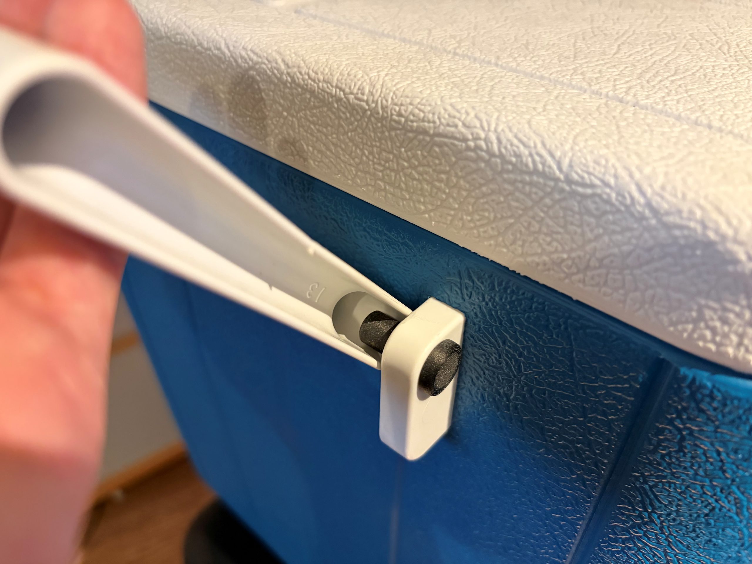
Once the two parts were printed, they were installed in their respective locations. A few quick tests confirmed that the handle functioned perfectly, just as if the cooler were brand new.
That was when my colleague told me, “Your cooler is ready.”
The moment I had been waiting for.
For me, it was the satisfaction of having made a great purchase while staying within budget and meeting the BBQ deadline. For Charles-Olivier, it was the satisfaction of solving a practical problem using precise measurements, SOLIDWORKS, and his secret weapon: a Markforged 3D printer.
The savings were significant. The pair of replacement parts cost approximately $1.50 CAD to produce, compared to the potential cost of ordering replacement parts with shipping fees or purchasing a brand-new cooler.
How 3D Printing Reduces Costs and Lead Times
In an industrial setting, the parts involved can represent equipment worth thousands or even tens of thousands of dollars.
3D printing stands out because of its flexibility and rapid production capabilities. When the availability of a replacement part becomes a challenge and a solution is needed quickly, additive manufacturing truly demonstrates its value.
Extending the lifespan of products not only helps reduce costs but also contributes to more sustainable and responsible practices.
To learn more about additive manufacturing and the Markforged solutions offered by SolidXperts, visit: 3D Printing and Scanning Solutions – Solidxperts

Any questions? Need help? Ask one of our experts.
Whether you’re ready to get started or just have a few more questions, you can contact us toll-free:


