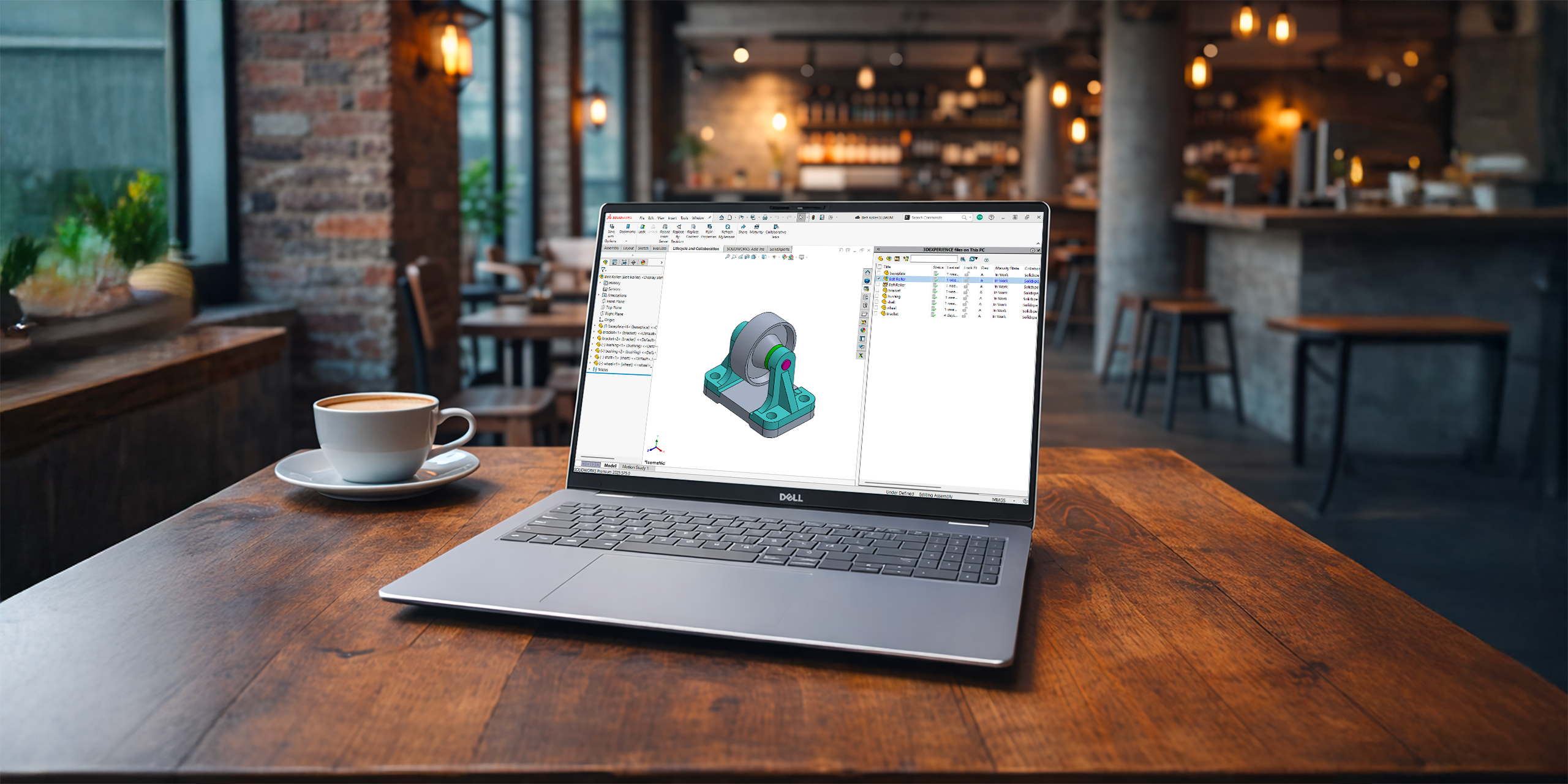
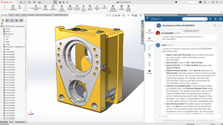
One of the biggest advantages of the 3DEXPERIENCE platform is having your files stored securely in the cloud. You can access your designs anytime, anywhere, and collaborate with teammates without worrying about version control.
Behind the scenes, SOLIDWORKS uses a local cache, a folder on your computer where files are temporarily stored while you work. These cached files are then synced with the 3DEXPERIENCE servers when you save or refresh.
Managing this cache is key to keeping your designs current, preventing confusion, and saving disk space. Let’s take a closer look.
Where to Find the 3DEXPERIENCE Cache
Think of 6W Tags as smart labels that make it easy to filter, sort, and find your files in 3DSpace or 3DDrive.
Your cache shows up both in SOLIDWORKS (via the 3DEXPERIENCE add-in) and in Windows Explorer. While you can browse the cache folders directly, we don’t recommend managing them that way. Instead, stick to the tools built into SOLIDWORKS.
Here are the default folder locations:
SOLIDWORKS Desktop with the 3DEXPERIENCE add-in: C:\3DEXPERIENCE
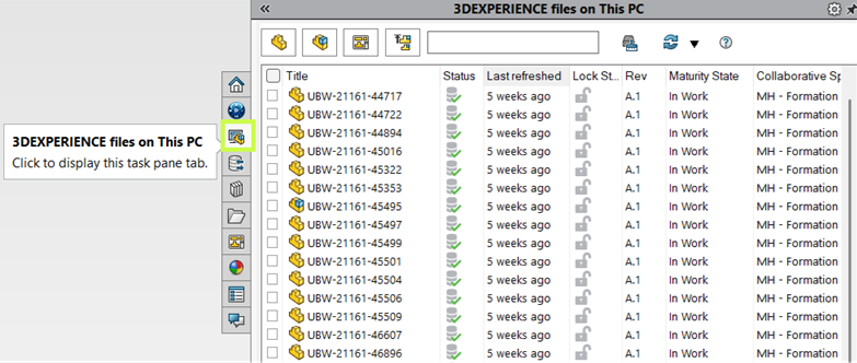
When you enable the “3DEXPERIENCE Files on This PC” add-in, you’ll see a dedicated tab in the Task Pane. This view shows you all cached files with helpful details like:
Status
Lock Status
Maturity State
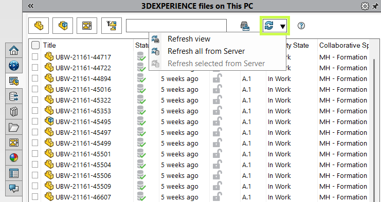
From here, you can quickly refresh your cache to make sure you’re always working with the latest version.
Refresh View updates the local cache for selected files.
Refresh from Server checks for changes made by other users and downloads the latest copy if needed.
Starting a new SOLIDWORKS session automatically refreshes files in the background.
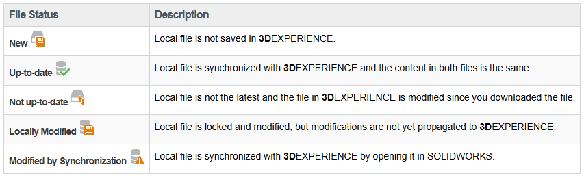
Understanding Cache Status Icons
The status icons make it easy to tell if your local files are current, out-of-date, or waiting to be uploaded. They also warn you if refreshing would overwrite changes you’ve made locally.
Pro tip: Always double-check before reloading from the server. Unsaved local edits will be lost.
Cleaning Up the 3DEXPERIENCE Cache
Over time, cached files can pile up and take up space. To keep things tidy (and ensure you’re pulling the latest versions from the cloud), it’s a good idea to clean your cache periodically.
Here’s how:
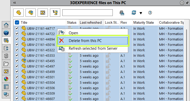
In the Task Pane, select individual files, or use the top-left checkbox to select all.
Right-click and choose “Delete from this PC.”
This only removes files from your local cache. Your data stays safe in the 3DEXPERIENCE platform.
You can also use:
Filters to find specific file types.
The search box to locate files quickly.
And before you delete, always confirm your files are saved and synced to the platform.
Automating Cache Clean-Up
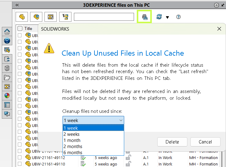
Don’t want to do it manually? The Clean Up command takes care of it for you.
By default, it removes unchanged files older than one week.
Locked or modified files won’t be touched.
If you open an assembly later, any missing references are automatically redownloaded from the server.
If disk space isn’t a concern, you can extend the timeframe to reduce how often files get cleared. It is especially useful if your internet connection is slow.
A Simple Habit for Staying Up to Date
The local 3DEXPERIENCE cache is like a bridge between your desktop and the cloud. Keep it clean, refresh it often, and you’ll always know you’re working with the latest designs.
Want to get even more out of your 3DEXPERIENCE platform? Our training sessions are designed to help you and your team take full advantage of its powerful tools.
The 3DEXPERIENCE platform isn’t just about CAD in the cloud. It’s your all-in-one workspace where design, data management, and collaboration come together. Whether you’re sketching with xShape, modeling in xDesign, or connecting to SOLIDWORKS, the platform helps keep everything, and everyone, in sync.
But let’s be honest: every engineering project generates mountains of data. 3D models, drawings, BOMs, simulations, even invoices and Word docs. It all piles up. The good news? The platform makes it easy to organize and navigate this information with a powerful tool called 6W Tags.
What Are 6W Tags?
Think of 6W Tags as smart labels that make it easy to filter, sort, and find your files in 3DSpace or 3DDrive.
And it’s not just CAD data. Office documents, simulation results, and more can all benefit from tagging.
Here’s how the 6Ws break down:
What: Type of content (CAD models, documents, simulations, tasks, etc.)
Who: The person who uploaded, edited, revised, or owns the data
When: Date or time range
Where: Geolocation or data source
How: Manufacturing method (made in-house or purchased)
Why: Links to project or task management
Out of the box, the system automatically fills in basics like owner, location, and save date. But the real power comes when your team adds custom tags. For example, you can include project numbers, material types, or vendor names so searches are tailored to your company’s workflow.
How to Use 6W Tags
Let’s say you search for “bolt” in 3DEXPERIENCE. Without filters, you might get hundreds (if not thousands) of results. That’s where 6W Tags shine.
Click the tag icon next to the search bar, then start narrowing your results. For example:
Under What, choose Physical Product (to exclude tasks or documents).
Add a Material filter for Stainless Steel.
By stacking filters, your results go from overwhelming to precise in just a few clicks.
Real-World Examples
In one test, a simple search brought back over 1,000 results. But after filtering with 6W Tags for “Physical Product” and “Plain Carbon Steel,” the number of results dropped down to two digits. That’s the power of smart filtering.
Beyond search, 6W Tags can be used visually inside apps. For example, parts can be color-coded by material in the graphics area, giving you an instant overview of your design.
From Data Overload to Data Control
Data shouldn’t slow you down and with 6W Tags, it won’t. Whether you’re hunting down a single file or organizing entire projects, the 3DEXPERIENCE platform helps you stay in control.
Want to learn more tips like this? Our experts at Solidxperts can help you get the most out of your 3DEXPERIENCE environment. Reach out anytime or join one of our training sessions!
One of the biggest strengths of the 3DEXPERIENCE platform is how it brings your team together. With SOLIDWORKS Cloud Services, you get built-in data management, making it simple to collaborate with colleagues, keep projects organized, and even access your designs on the go.
Whether you’re working in SOLIDWORKS Connected or traditional SOLIDWORKS combined with Collaborative Designer for SOLIDWORKS, you have a direct link to the 3DEXPERIENCE platform, so opening, saving, and managing your model data feels seamless.
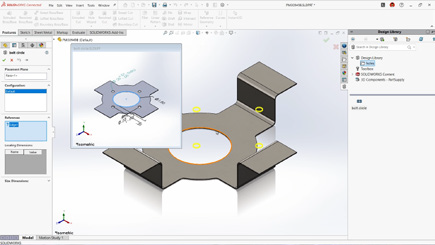
But here’s the thing: design work goes beyond just parts and assemblies. You also rely on libraries, weldment profiles, sheet metal gauge tables, templates, routing components, and more. Keeping those libraries in sync across your team is just as important as managing your models. And with 3DEXPERIENCE, you can centralize those libraries too.
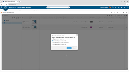
Step 1: Create Your Library Structure
Start in the Bookmark Editor app (in your web browser). Create a clean folder structure for your templates and libraries, with subfolders for each type. Then, simply drag and drop your files into place.
This way, your team has one organized hub for all shared resources.
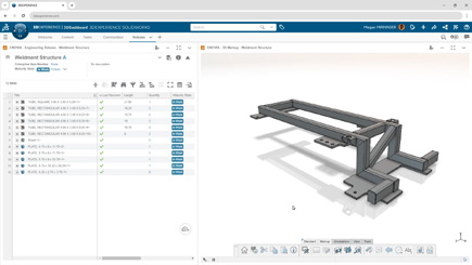
Step 2: Set Up Weldment Profiles
For weldments, it’s best to stick with a consistent naming convention: Standard → Type → Size.
We also recommend customizing your standard names to keep them separate from the defaults SOLIDWORKS provides. For example, you might create a standard called “Xperts – ANSI Inch”.
Once you’ve named things properly, drag your weldment profile files (or entire folders) from Windows File Explorer directly into your 3DEXPERIENCE bookmark. Quick, easy, and ready to use.
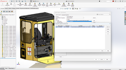
Step 3: Connect Libraries to SOLIDWORKS
Inside SOLIDWORKS, go to System Options → File Locations. When you add a new location, choose “Select from 3DEXPERIENCE”.
This links SOLIDWORKS to your bookmarks, syncing the content down to your local cache (usually found at C:\Users\Public\Documents\SOLIDWORKS). You’ll notice the linked locations show up in brackets, confirming they’re tied to the platform.
To make sure you’re always up to date, just click Update. SOLIDWORKS will pull the latest versions from 3DEXPERIENCE, keeping your whole team in sync.
Step 4: Keep Your Libraries Updated
Need to update a file? Head back into the Bookmark Editor in your browser, right-click the file, and select Update. Browse for the new version locally, and the platform will take care of the rest.
Once it’s updated in 3DEXPERIENCE, users just need to hit Update in their SOLIDWORKS options to refresh their local cache. Simple, controlled, and consistent.
Why This Matters
Storing your libraries and templates alongside your design data gives you the same benefits: revision control, lifecycle management, and a single source of truth for your team.
We focused on weldment profiles here, but the same approach works for routing components, sheet metal gauge tables, and more. With SOLIDWORKS Cloud Services + 3DEXPERIENCE, you’re not just managing files. You’re creating a smarter, more connected workflow for your entire team.
At Solidxperts, we love helping teams get the most out of their tools. Setting up your libraries in 3DEXPERIENCE is a small step that makes a big impact on collaboration, efficiency, and design quality.
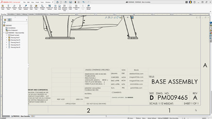
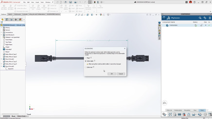
Backing up your data is always a smart move. The good news is that the 3DEXPERIENCE platform already includes secure cloud storage, but sometimes you may want to create a local, on-site backup as well.
To help you do that, this guide walks you through two options:
1. Exporting one project at a time (top-level assembly in its own .zip file)
2. Exporting everything together (all data in a single .zip file)
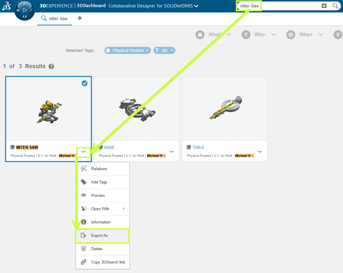
Option 1: Export a Single Project
This method is perfect if you only need to back up a specific assembly or project.
1.Use the search field at the top of your session (or the Bookmark Editor, if you’ve bookmarked the file) to locate your top-level assembly.
2. Select the assembly (it will highlight in blue when chosen).
3. Click the chevron (arrow) to the right of the file.
4. Choose Export As.
5. Continue with the export steps outlined in the final section of this guide.
Option 2: Export Everything at Once
Heads up: If you have a large dataset, this method can produce a very large zip file. For performance reasons, we often recommend Option 1, exporting project by project.
But if you do want the full export, here’s how:
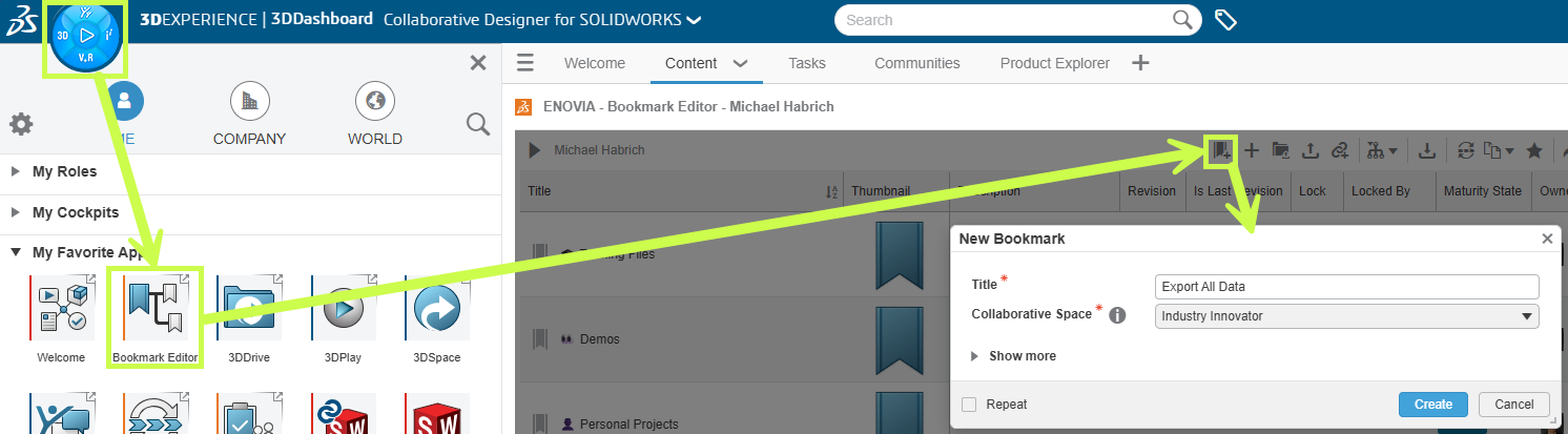
1.Open the Bookmark Editor app.
Create a new bookmark called something intuitive, like Export All Data.
Leave Bookmark Editor open with your new bookmark selected.
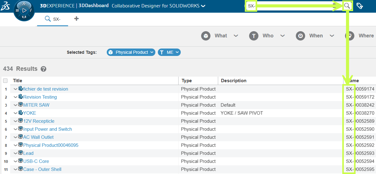
2. In the search bar, type “prd” (default naming convention).
If your company uses a different convention, use the keyword that applies to your setup (e.g. SX- for Solidxperts).
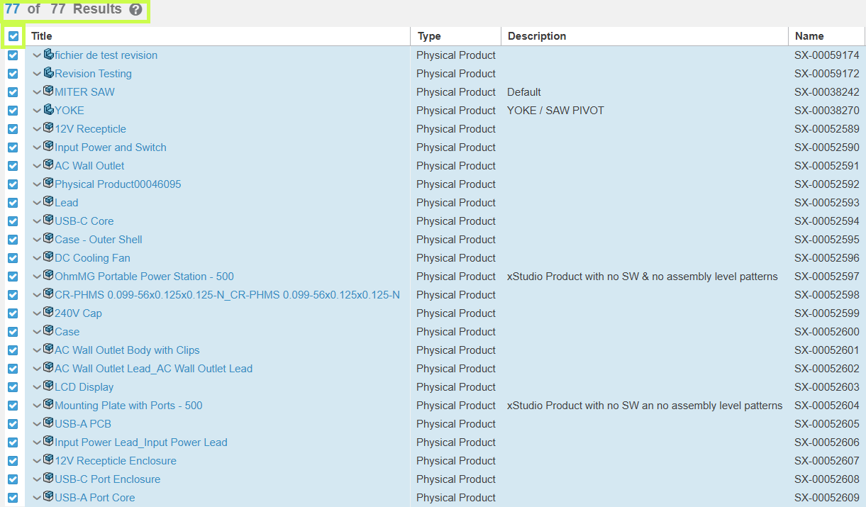
Double-check the counter to ensure all items are selected. (If numbers don’t match, scroll to the bottom and re-select.)
5. Drag the selected files into your export bookmark.
This applies the bookmark to all selected items.
If you have a lot of files, give the system time to process.
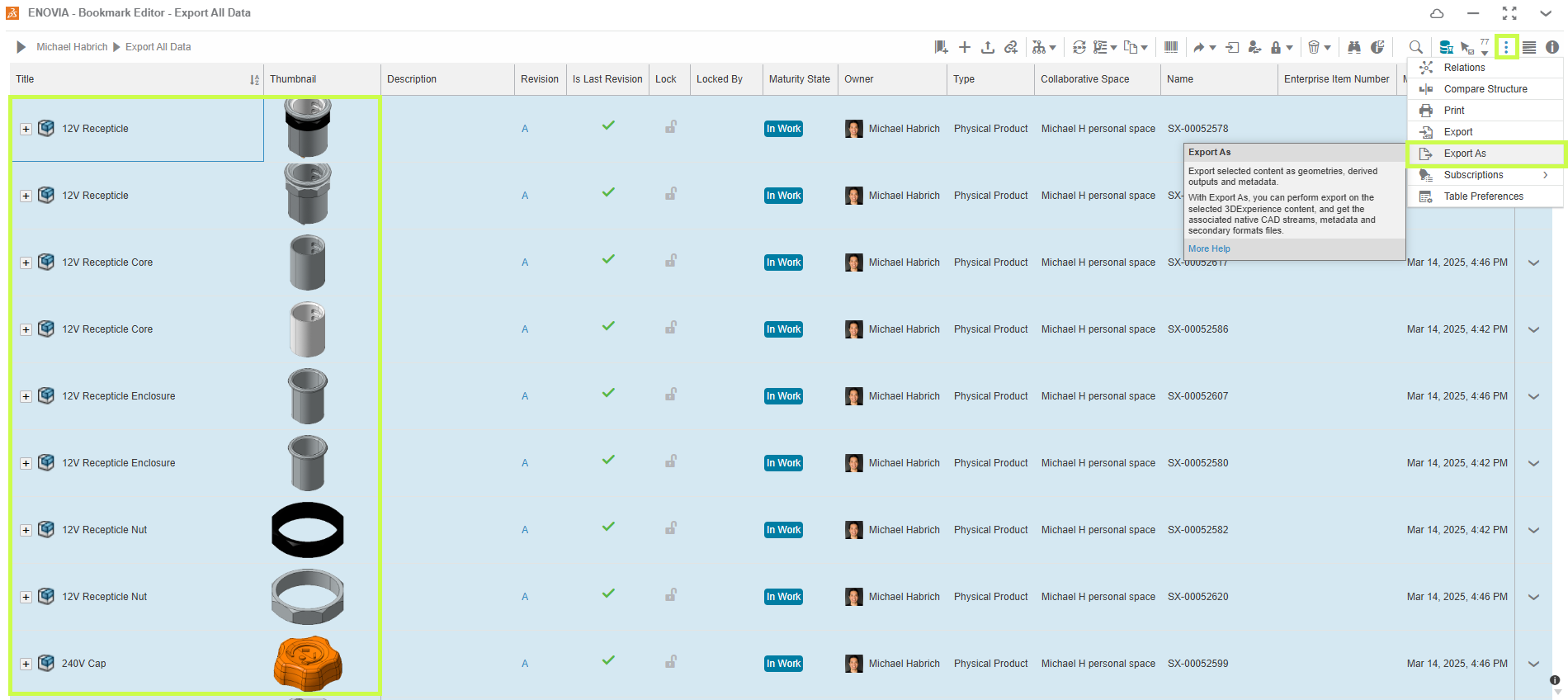
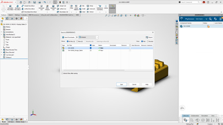
6. Back in Bookmark Editor, group-select the files you want to export (Ctrl+A for all).
7. Click the 3 dots (⋮) in the upper right → choose Export As.
8. In the Export As dialog:
Give your .zip file a clear title.
Optionally, check Include Drawing.
Confirm the item count. If it looks low, scroll to the bottom of Bookmark Editor to refresh, then try again.
Review any exclusions in red . These could be xApp-created files (like xDesign) that aren’t currently exportable.
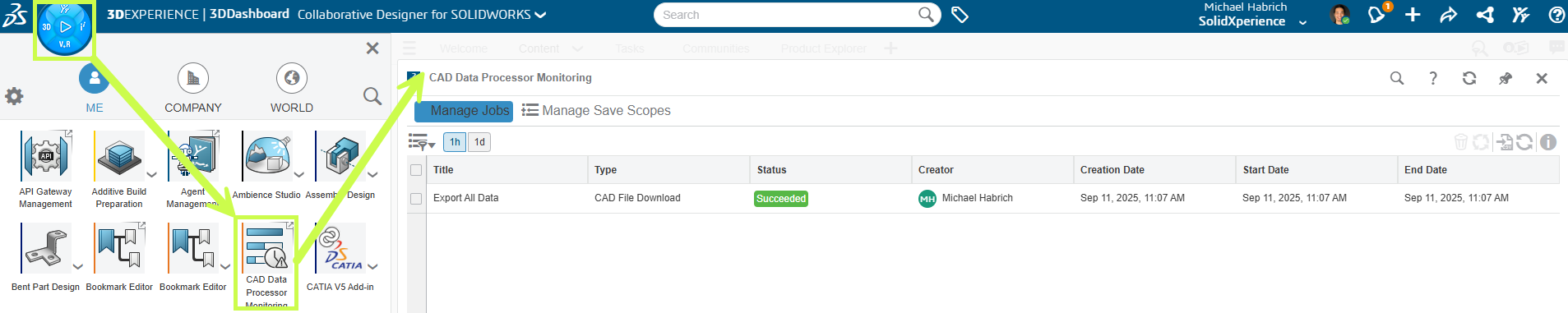
9. The system creates an export job.
You can monitor large jobs in the CAD Data Processor Monitoring app.
Smaller jobs often finish before they appear there.
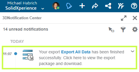
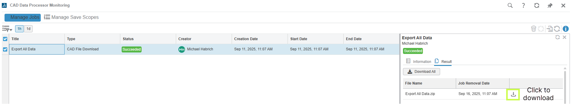
10. Once complete, you’ll see a notification in the 3DNotification Center.
11. Click the notification, then hit Download to retrieve your .zip file.
Pro tip: Test the process with a small dataset first so you’re comfortable before running a full export.
Wrapping Up
Ultimately, with just a few steps, you can create local backups of your 3DEXPERIENCE projects, whether it’s one assembly at a time or your entire dataset.
Beyond the backup process, at Solidxperts, we help teams like yours work more confidently with 3DEXPERIENCE every day. If you’d like hands-on training or tailored backup strategies, our experts are here to guide you.
At Dassault Systèmes, keeping your account secure is a top priority. That’s why two-factor authentication (2FA) is now required when you access the DSx Client system.
What does this mean for you? In short: an extra layer of protection for sensitive data like user information and serial numbers. It also means a quick setup process the first time you log in and after that, peace of mind knowing your account is more secure.
This guide will walk you through:
How to set up 2FA on your phone (most common method).
How to set up 2FA on your computer using KeePassXC if you prefer not to use a mobile device.
Option 1: Setting Up 2FA on Your Phone
1. Download an Authenticator App
If you don’t already have one, install an authenticator app such as Google Authenticator, Microsoft Authenticator, or Okta.
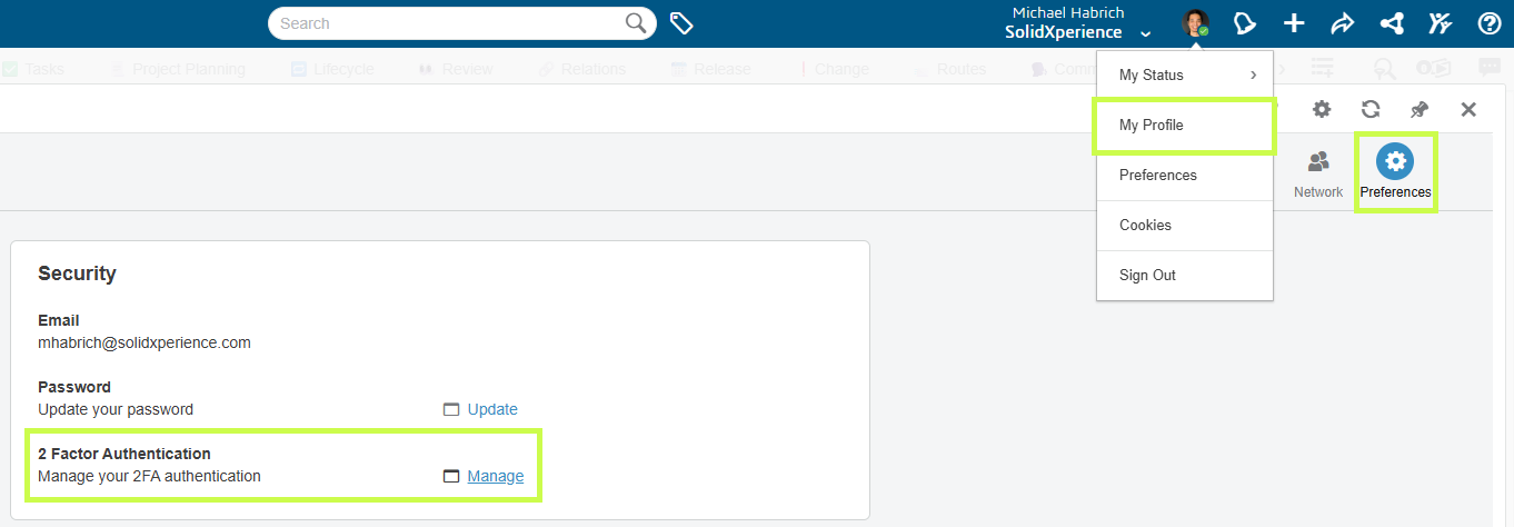
From your account, click My Profile > 2-Factor Authentication.
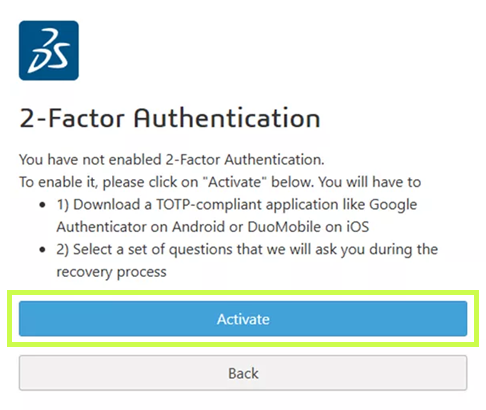
4. Activate 2FA
Select Activate to begin setup.
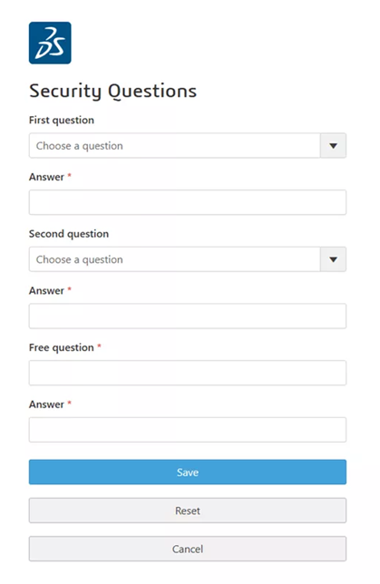
5. Set Recovery Options
Answer the required security questions. These will be used if you ever lose access to your 2FA device.
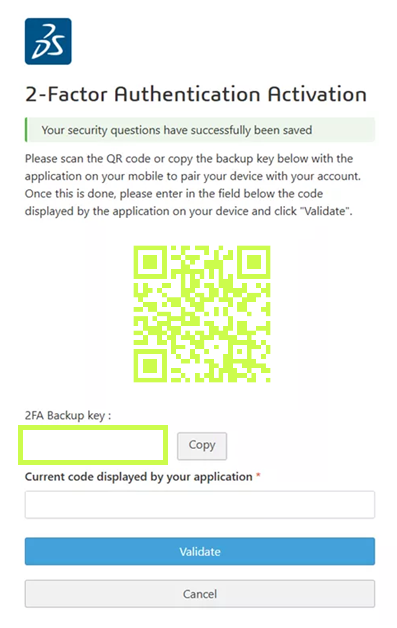
6. Connect Your Authenticator
In your authenticator app, choose Scan a QR Code (or Enter a setup key if your phone has no camera). Scan the code provided by Dassault Systèmes.
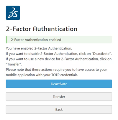
7. Test and Confirm
Your authenticator will display a 6-digit code. Enter it into DSx Client to confirm setup. Once successful, you’ll see a confirmation window — 2FA is now enabled! 🎉
Going forward: Every time you log into DSx Client, you’ll be asked for a code from your authenticator app.
Option 2: Setting Up 2FA on Your Computer (KeePassXC)
Prefer not to use your phone? No problem. You can configure 2FA directly on your computer with KeePassXC, a secure, open-source password manager.
1. Download and Install KeePassXC
Available for Windows, macOS, and Linux at KeePassXC’s website. Default installation options work fine.
2.Create a Database
This is where your passwords and tokens are stored. Set a strong master password and keep it in a safe place.
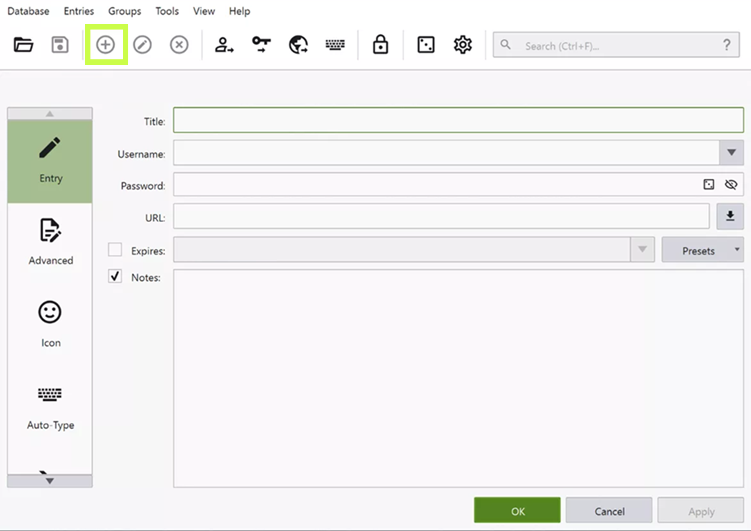
3.Add a DSx Client Entry
Create a new entry with:
Title: DSx Client
Username, Password
URL: https://dsxclient.3ds.com
4. Set Up the 2FA Key
Right-click your new entry > Setup TOTP. Enter the secret key provided in DSx Client (same as in the phone setup).
5. Test and Confirm
Click the clock icon next to your entry to generate a 6-digit code. Enter it in DSx Client. Once confirmed, your 2FA is ready to go.
Wrapping Up
That’s it! You’ve now secured your DSx Client account with two-factor authentication. Whether you chose to set it up on your phone or on your computer, you’re adding an important layer of protection to your Dassault Systèmes tools.
And remember, if you hit a bump along the way, the Solidxperts team is always here to help. Reach out to us, and we’ll make sure your account stays safe and your workflow stays smooth.
SOLIDWORKS PDM is a powerful tool for managing product data, but like any system, it is only as good as its implementation. Missteps in setup, usage, or governance can result in lost time, confused teams, or even corrupted data. Let’s break down the top five mistakes users and administrators make with SOLIDWORKS PDM and provide expert-backed solutions to fix them.
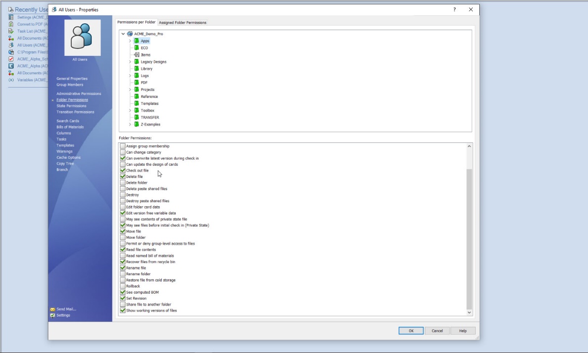
1. Don’t Let Permissions Kill Productivity
SOLIDWORKS PDM folder permissions tab, detailing access rights within the vault. The interface displays a folder tree and a checklist of enabled actions.
The Pitfall: Confusing or Dangerous Access Rights One of the most frequent and damaging mistakes in any PDM setup is mismanaging user permissions. When permissions are too strict, users waste time trying to access files or wait for someone with higher access to help. On the flip side, overly broad access can result in accidental overwrites, deletions, or unauthorized changes. For example, an engineer could accidentally releases a work-in-progress drawing because they were mistakenly given access to the “Released” state transition. This leads to procurement ordering incorrect parts based on an outdated design.
The Fix: Implement Role-Based Access Control (RBAC) Instead of managing individual user permissions, create user groups such as:
Designers
Engineers
Quality Control
Project Managers
Manufacturing
Assigning permissions at the group level simplifies administration but also ensures consistency. If someone’s role changes, you just move them between groups.
Best Practices:
Use the Permissions tool in PDM Admin to verify access levels
Restrict access to critical lifecycle transitions (e.g., “Approve,” “Release”)
Re-audit access rights quarterly, especially after organizational changes
Keep a changelog of all admin updates to permission groups
Why it matters:
Tight control over permissions protects data integrity, reduces user frustration, and limits the risk of human error.
2. Are Your Workflows Helping or Hindering?
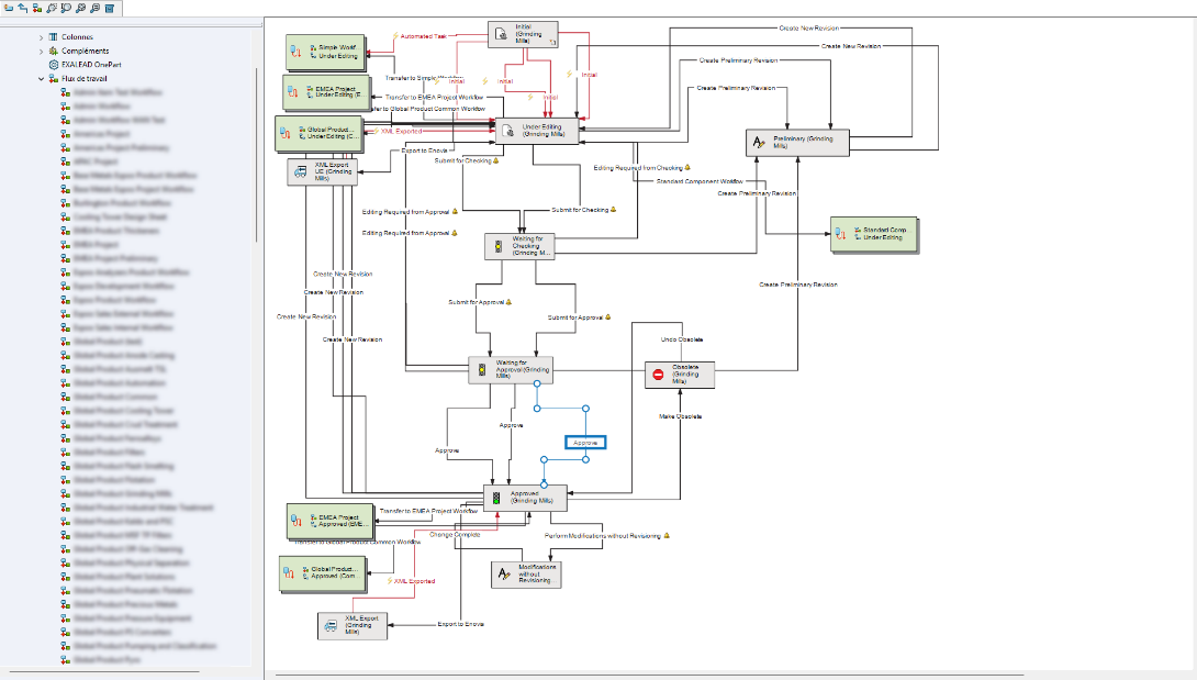
A highly detailed and customized SOLIDWORKS PDM workflow, illustrating the lifecycle of engineering files, workflows like this can introduce challenges in usability, maintenance, and onboarding, highlighting the importance of balancing control with simplicity in PDM design.
The Pitfall: Workflows That Don’t Reflect Real-Life Processes
Another common issue is poorly designed workflows. Often, workflows are either overly simplistic and fail to enforce proper checks or overly complicated, leading to user confusion and delays. For example, a workflow without a design review stage results in errors reaching production. Alternatively, a workflow with too many approval loops creates a bottleneck that delays time-to-market.
The Fix: Design Smart, Flexible Workflows
Good workflows reflect how your team actually works. Start by mapping out real-world processes on paper. Then replicate those with SolidWorks PDM using tools like:
Conditional Transitions
Automatic Status Changes
Notifications (via Dispatch or Task Add-ins)
Pro Tips:
Include mandatory review steps before “Release”
Create a sandbox or test vault to trial new workflows without disrupting production
Practice using screen recordings or internal guides to walk through common workflows. Even the best workflow cannot help if users don’t understand it.
3. Stop the Chaos: Fix Your Revision Control
The Pitfall: Manual File Naming and Confused Versioning
Few things frustrate engineers more than working on the wrong version of a file. Common issues include:
Duplicate files with suffixes like _final, _v2, _approved
Broken references from renamed assemblies
No clear revision history when questions arise
For example, a supplier receives an outdated drawing marked “FINAL_v3,” but the design team had already created “FINAL_v4” in a separate folder. Which results in countless dollars wasted and scrap material.
The Fix: Use PDM’s Automated Version and Revision Tools
SOLIDWORKS PDM is built to manage versions and revisions intelligently when used properly. By integrating revision control into your workflow transitions, you can track every change and automatically increment revisions when files pass certain gates such as “Approve.”
Steps to Implement:
Set up lifecycle states (e.g., Under Review → Approved → Released)
Configure transitions to increment revisions automatically
Use the built-in History tab to track who made what changes and when
Apply revision tables linked to metadata to eliminate manual edits on drawings
Important Tips:
Disable file renaming at the user level
Avoid copying files outside PDM to test changes; instead, use sandbox folders within the vault
Regularly purge obsolete versions to avoid clutter
Result:
Accurate, tamper-proof versioning builds trust across design, QA, and manufacturing teams.
4. Organize or Agonize: Clean Up That Vault
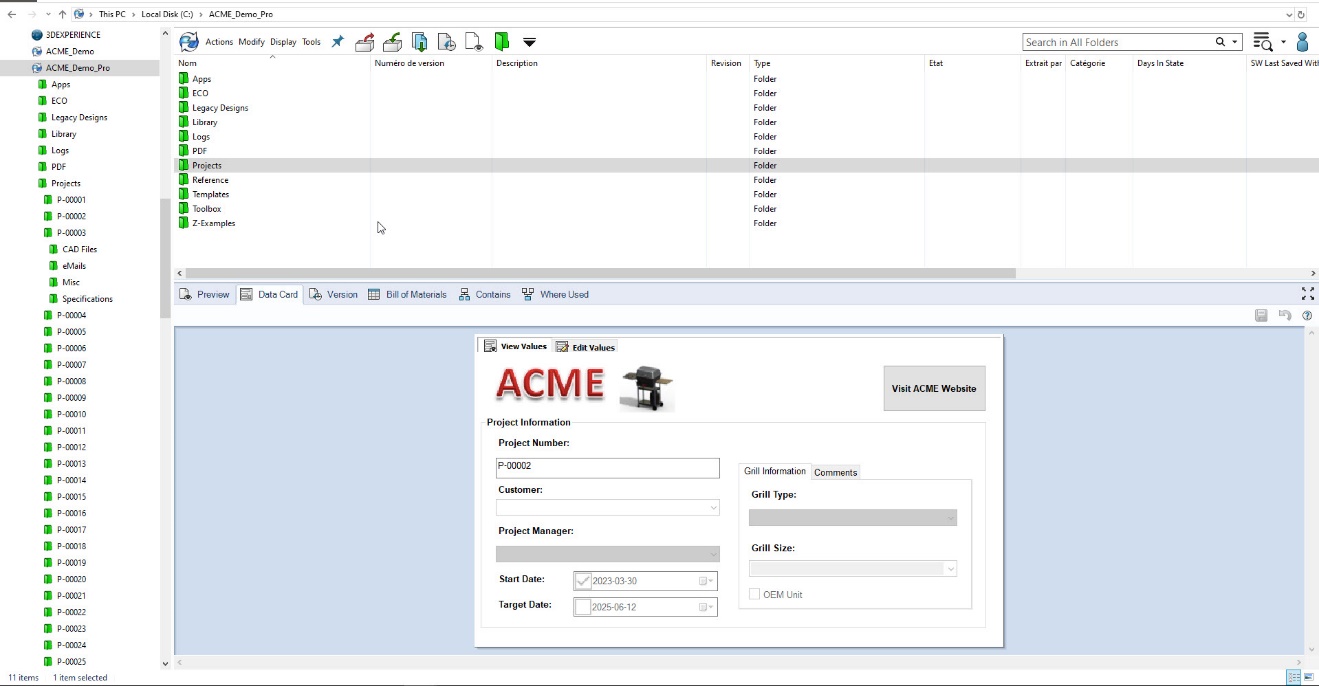
SOLIDWORKS PDM Vault interface, featuring a typical folder structure on the left and project metadata displayed in a custom data card below.
The Pitfall: Messy Folders, Inconsistent File Names, and Confusing Structures
Without naming conventions or a logical file system, even experienced users can spend hours hunting for the right file or, worse, use the wrong one.
For example, a project folder contains new_final, revA_drawing, Drawing1, and final_FINAL. No one knows which to use, and a new engineer duplicates the wrong one for a new design.
The Fix: Standardize File Naming and Folder Structures
Consistency is key to finding and managing data efficiently. Develop a file naming convention that reflects your project hierarchy and revision status.
Sample Naming Structure:
PRJ2025_ClampBracket_REV_B.SLDPRT
DWN1001_ClampBracket_REV_B.SLDDRW
Tips to Maintain Order:
Enforce naming rules with Data Cards
Use “Copy Tree” for project duplication to auto-rename and preserve links
Document your structure in an internal wiki or onboarding guide
Bonus:
Create folder templates tied to project types (e.g., Customer Jobs, R&D, Internal Use) to speed up setup and reduce human error.
5. One Crash Away: The Backup Plan You Wish You Had
The Pitfall: No Backup or Worse, Unusable Backups
It is easy to assume your IT team has your back until a vault crash or server failure proves otherwise. Even if backups exist, they may be incomplete, outdated, or impossible to restore. For example, your server crashes on a Friday night. IT discovers that the last backup was from three weeks ago and only covers the SQL database, not the archive files.
The Fix: Build a Complete, Tested Backup and Recovery Plan
A proper backup strategy must cover all components of SOLIDWORKS PDM:
SQL Database
Archive Server
Vault Settings (via the Admin tool)
Checklist for Backup Success:
Back up daily using Windows Task Scheduler or enterprise tools
Store backups off-site or in the cloud for disaster recovery
Simulate a full restore every quarter and document the steps
Disaster Recovery Plan Should Include:
Contact info for key stakeholders
Timeline for each recovery step
Inventory of hardware and software requirements
A change log for vault structure
Crucial Question:
If a critical client asks, “How quickly can you restore if the vault crashes?” do you have an answer you trust?
Bonus Mistake: Skipping Training and Internal Communication
Even the best-configured PDM system will not deliver value if users do not understand how to use it. Inconsistent user behavior leads to data quality issues, broken workflows, and user frustration.
Fix it with:
Scheduled team-wide PDM refresher sessions
A living document library of video walkthroughs and SOPs
Feedback loops such as a Slack or Teams channel for PDM issues
Pro Tip:
Use anonymous surveys to surface pain points or confusion that might not come up in meetings.
Stop Mistakes Before They Start
SOLIDWORKS PDM is not just a file storage system. It is the foundation of your product development lifecycle. Like any foundation, it requires care, structure, and proactive management. By recognizing and correcting the most common PDM mistakes, whether it is permissions, workflows, revisions, organization, or backup planning, you set your team up for success.
Takeaway Checklist:
Role-based permissions
Streamlined, mapped workflows
Automated revision control
Standardized file and folder naming
Complete, tested backup plan
Ongoing user training
Each of these practices improves traceability, compliance, and efficiency. Saving you time, money, and stress in the long run.
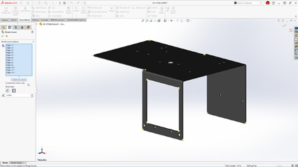
A few weeks ago, my SOLIDWORKS Elite Applications Engineer award fell, and the top part of it broke. I was both sad and frustrated. Sad because it meant something to me, and frustrated because I had placed it on a shelf that later tilted unexpectedly, sending everything crashing to the floor. Finding it broken on the ground that day was tough.
Accidents like this happen all the time. The products we design are also at risk of being dropped, so why not make them as resistant as possible?
That’s exactly where SOLIDWORKS Simulation drop tests come in.
In this guide, you’ll learn:
what a drop test is,
why drop test analysis is essential for product reliability,
and how to run a drop test in SOLIDWORKS Simulation step by step.
Why Drop Tests Matter for Product Design?
Any time a product is handled, shipped, carried, or installed, there’s a chance it could be dropped. A single impact can compromise safety, durability, performance, and sometimes even a company’s reputation.
Drop tests help engineers predict how their products will behave in real-world accident scenarios. Below are examples of industries where drop testing is essential to ensure reliability before manufacturing:
Consumer products & electronics
Industrial & heavy equipment
Medical devices
Sports equipment
Aerospace & aviation
Automotive & transportation
Military & defense
Packaging & logistics
Robotics & automation
Construction & civil engineering
Drop Test Prerequisites: What You Need Before Running a Simulation
Before running a drop test analysis, certain elements must be prepared. A 3D design is required to simulate the event digitally. Here are the steps:
Create the 3D model in SOLIDWORKS or import an existing geometry.
Apply materials (this step can also be performed directly in the study).
Simplify the model to reduce solving time (this may include suppressing non-critical parts or features).
How to Run a Drop Test Analysis in SOLIDWORKS Simulation
Once your model is ready, you can set up the drop test using the following steps:
Enable the SOLIDWORKS Simulation add-in.
Create a new Drop Test study.
Apply any missing material properties.
Define interactions if needed.
Set up the drop test conditions (drop height or impact velocity, orientation, ground parameters, etc.).
Adjust result options (duration after impact, saving options, etc.).
Mesh the model and run the analysis.
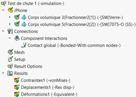
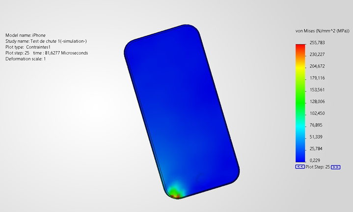
Interpreting Your Drop Test Results
After running the analysis, several result types become available, such as stress and deformation plots. These help you determine whether the product will remain elastic, undergo plastic deformation, or potentially fail, and where such failures are likely to occur.
The example below shows the kind of output SOLIDWORKS Simulation provides once the calculations are complete:
Improving the Design Through Simulation
Thanks to the results, you can identify weak points where the product is likely to fail. You can then reinforce the design. For example, by adding fillets, increasing wall thickness, or selecting a stronger material.
Sometimes, results show that a part is overdesigned. In these cases, you may reduce thickness or remove unnecessary material to lower weight and cost. This is a key step in optimizing your product.
Simply make the changes and re-run the drop test to validate the improvements.
Bringing It All Together: Stronger Designs Through Simulation
With SOLIDWORKS Simulation, you can test your product digitally long before manufacturing it. A drop test is just one of many analysis types available to help you validate performance and reliability.
I initially blamed myself for the broken award, but maybe if the shelf had been designed to be stronger, the accident could have been avoided. Who knows?
From linear static to nonlinear dynamic analyses, SOLIDWORKS Simulation provides a complete suite of tools to help engineers validate their designs efficiently. At Solidxperts, we are committed to helping our customers achieve excellence in their engineering projects.
Looking to sharpen your skills? Browse our upcoming trainings, available at our offices or online. Whether you’re new to simulation or ready to deepen your expertise, our certified specialists are here to support you every step of the way.
SOLIDWORKS 2026 delivers a wave of powerful enhancements designed to accelerate collaboration, streamline data management, and strengthen connectivity across design teams. From AI-driven support to enterprise-grade approval workflows, every improvement empowers engineers, designers, and manufacturers to work faster, smarter, and more seamlessly together.
Top 10 Enhancements You Need to Know
1. AURA Integration in 3DSwym
AI meets collaboration. With AURA integrated directly into 3DSwym, users can instantly summarize posts, wikis, and Q&As or pull in insights from entire discussions to drive smarter conversations.
These enhancements deliver faster insights and more informed collaboration with less manual searching.
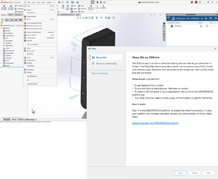
2. Collaboration Directly Inside SOLIDWORKS
Work together without ever leaving your design space. Collaborate through the SOLIDWORKS User Forum, share files via 3DDrive and 3DSwym, and eliminate the need for conversions or third-party tools.
These enhancements deliver smoother teamwork and more efficient communication with less switching between tools.
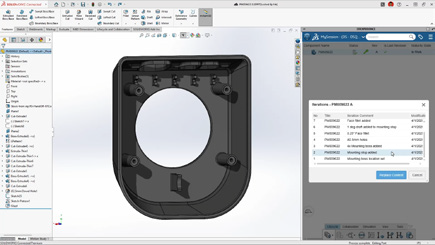
3. Drawing Stamping with Maturity Status
Simplify change management with automatic maturity status stamps. User names and emails are embedded in drawings for full traceability and accountability throughout the design lifecycle.
These enhancements deliver clearer documentation and more reliable approvals with less manual tracking.
4. Cut List Management on the 3DEXPERIENCE Platform
Cut list data can now be fully managed on the platform, enabling tighter integration between EBOM and MBOM.
These enhancements deliver better alignment between design and manufacturing with less data re-entry.
5. Recent Files by Active Tenant
For teams managing multiple tenants, SOLIDWORKS 2026 now filters your recent files to show only those from the active tenant.
These enhancements deliver cleaner organization and faster access with less confusion.
6. Excel File Management for Design Tables
Design table management is now more reliable thanks to Excel file support on the 3DEXPERIENCE platform. This ensures version consistency, better automation, and stronger data integrity.
These enhancements deliver greater consistency and more reliable design automation with less manual version control.
7. Support for Deformable Components
Easily switch between rigid and deformed part states in assemblies for improved accuracy and flexibility.
These enhancements deliver faster detailing and more accurate assemblies with less manual effort.
8. Automatic Bookmark Content Updates
Bookmarks now update automatically each session, ensuring you always access the latest design data, no manual refresh needed.
These enhancements deliver up-to-date project information with less time spent managing data.
9. Enhanced Bookmark Editor
A redesigned Bookmark Editor delivers faster navigation and smarter selection when multiple bookmarks exist.
These enhancements deliver clearer navigation and more accurate project organization with less manual searching.
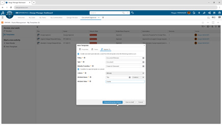
Large organizations gain new governance power with automated approval workflows tied to document maturity. Predefined routes trigger automatically for consistent, traceable, and compliant approvals.
These enhancements deliver stronger governance and more reliable approvals with less administrative overhead.
A New Standard for Collaboration and Data Management
SOLIDWORKS 2026 builds on its legacy of innovation with a sharper focus on collaboration, automation, and traceability. These ten enhancements don’t just make design faster, they make teamwork more intelligent, connected, and efficient across every stage of product development.
Join our official SOLIDWORKS 2026 launch to see these new features in action and get your questions answered by our experts!
SOLIDWORKS 2026 continues the trend of making design faster, smarter, and more connected. With AI-powered tools, streamlined workflows, and deeper collaboration features, this release is all about helping engineers and designers work more efficiently while maintaining accuracy and flexibility.
Here are the Top 10 Enhancements you need to know:
1. AI-Powered Design and Detailing
Artificial intelligence is making a real impact in everyday CAD workflows:
Automated drawing creation with AI-driven views, hole callouts, dimensioning, detailing, and even sheet format selection.
AI assembly recognition can now automatically detect and insert fastener-like components (nuts, bolts, washers), reducing repetitive tasks and improving assembly accuracy.
These enhancements deliver faster detailing and more accurate assemblies with less manual effort.
2. Large Assembly Performance
Large assemblies are now easier to manage:
Open massive designs faster by filtering only what you need from the 3DEXPERIENCE platform.
Skip rebuilds when only cosmetic changes are made.
Disable auto-resolve for lightweight components to improve responsiveness.
Together, these updates create smarter workflows that keep even the largest projects running smoothly.
3. Improved User Experience
Offline mode ensures uninterrupted productivity during internet disruptions.
A redesigned UI highlights common commands, helping new users get up to speed quickly.
Command Search now includes an expanded, customizable set of keywords.
The result is a smoother learning curve and less frustration for both new and experienced users.
4. Streamlined Part Design
Define a custom start point for sheet metal base flanges.
Break internal corners on folded geometry.
Quickly create square sketch geometry in one click.
Track maturity changes and drawing history with Evaluated Attributes.
These improvements enable faster sketching and greater flexibility in sheet metal design.
5. Collaboration & Data Management
Share designs directly via 3DDrive and 3DSwym.
Update files to the latest version on the 3DEXPERIENCE platform with a single action.
Access the SOLIDWORKS User Forum from within the software.
With these tools, staying in sync with your team and your data has never been easier.
6. Drawing Detailing & MBD
Insert Family Tables into drawings for configuration details.
Use magnetic lines to align not just balloons, but notes, weld symbols, and other annotations.
Propagate DimXpert dimensions to library features and selectively manage annotation visibility.
This gives designers more control and clarity when documenting their designs.
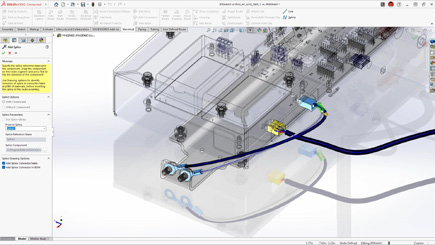
7. Routing, Electrical, and Piping
Combine routing BOMs across subassemblies for a clearer overall materials list.
Place clips, mounts, and hangers directly in assemblies for flexible routing.
Visual indicators help guide splice placement in harnesses and wire bundles.
This gives designers more control and clarity when documenting their designs.
8. Rendering Enhancements
Control tessellation for a balance of geometry quality and performance.
Improved denoising in CPU mode reduces render noise in fewer passes.
Expanded format support with PBR materials in USDZ and glTF.
This gives designers more control and clarity when documenting their designs.
9. ECAD/MCAD Collaboration
Track parent/child PCB data like keep-in, keep-out, plated and non-plated holes.
Use CircuitWorks™ with IDX 3.0 support to review and even undo MCAD changes before final ECAD updates.
This gives designers more control and clarity when documenting their designs.
10. Import/Export
Simplify complex multibody parts faster by using advanced selection tools to efficiently isolate and manage bodies based on similarity or size.
Share assemblies saved on the 3DEXPERIENCE platform using the Export as Package option in the Share dialog box.
Streamline exports by choosing whether to include drawings in your package, for greater control.
This gives designers more control and clarity when documenting their designs.
Final Thoughts
With AI-powered automation, large assembly improvements, smarter part tools, and seamless collaboration, SOLIDWORKS 2026 makes it easier than ever to move from concept to finished product. Whether you’re creating complex assemblies, detailing drawings, or collaborating across disciplines, this release delivers tools to help you work smarter, faster, and with greater confidence.
Take your designs to the next level with SOLIDWORKS 2026. Contact us today to unlock smarter, faster, AI-powered engineering.
When we talk about AI, certain fears arise: could AI replace the engineer or the designer? The answer is no. Dassault Systèmes’ philosophy is very clear: AI does not replace, it enhances. After 11 years at S0lidxperts and more than 15 years of using SOLIDWORKS, I am well aware of this fact.
SOLIDWORKS, one of the most trusted CAD platforms globally, has already begun integrating AI-driven tools that assist engineers in reducing repetitive tasks, improving design quality, and accelerating time-to-market. Through the 3DEXPERIENCE platform, Dassault Systèmes is also paving the way for AI-powered collaboration and predictive design in the cloud.
In this article, we’ll explore how AI is shaping the present and future of SOLIDWORKS, highlight the business benefits, and share how Solidxperts, over 40 years in the industry and more than 25 years as a SOLIDWORKS partner, supports companies in embracing this transformation.
1. AI in SOLIDWORKS: An Engineer’s New Ally
Dassault Systèmes’ vision has always been clear: AI does not replace engineers. It enhances their capabilities. For decades, SOLIDWORKS has incorporated automation features designed to simplify CAD workflows:
Smart Mates for automatic assembly constraints.
Command Prediction suggesting the most likely next tool.
These were early steps toward intelligent CAD. Today, SOLIDWORKS goes further with AI-driven assistants like Design Assistant, and cloud-based tools powered by machine learning through the 3DEXPERIENCE platform.
The philosophy is simple: let AI handle the repetitive and time-consuming tasks, so engineers can focus on innovation, creativity, and solving real engineering challenges.
2. Current AI-Driven Features in SOLIDWORKS
a) Design Assistant
Mate Helper and Selection Helper: automatically detects similar components and applies constraints, drastically reducing clicks in large assemblies.
Example: When assembling dozens of fasteners, Design Assistant identifies similar geometry and instantly applies consistent mates.
b) Automatic Drawings (SOLIDWORKS 2025)
Automatically generates 2D drawings from 3D models.
Ensures compliance with drawing standards.
Saves significant time in documentation, especially for design offices managing large projects.
c) Fastener Recognition (FD03)
Automatically detects standard fasteners in assemblies.
Applies appropriate mates without manual intervention.
Direct impact: reduced errors, fewer repetitive operations.
d) AURA: The Conversational AI Assistant
Integrated into the 3DEXPERIENCE platform.
Provides contextual guidance to users, learns from workflows, and offers predictive insights.
Example: guiding new users through advanced features or assisting with design standards.
3. The Future of AI in SOLIDWORKS: A Roadmap
Dassault Systèmes continues to push boundaries, and the AI roadmap promises groundbreaking advancements:
Mesh to Parametric Conversion (Reverse Engineering): AI will streamline converting mesh files into fully parametric models, accelerating reverse engineering processes.
AI-Optimized Assemblies: Automatic detection of redundant constraints, performance optimization, and manufacturability checks.
AI-Generated Photorealistic Renders: Leveraging generative AI to instantly create marketing-ready visuals without lengthy manual rendering.
xDesign and Cloud-Ready AI: The 3DEXPERIENCE xDesign app represents the next generation of CAD: cloud-based, AI-enhanced, and fully collaborative.
Vision: Predictive, Collaborative CAD: An environment where the system anticipates design intent, suggests optimizations, and improves with each project.
4. Strategic Benefits for Companies
Adopting AI in SOLIDWORKS is not just about convenience—it drives measurable business impact:
Productivity: Significant time savings through automation of repetitive tasks.
Quality: Consistent designs, fewer human errors, and adherence to standards.
Innovation: Engineers gain more time to focus on R&D and creative problem-solving.
Competitiveness: Faster time-to-market and optimized workflows lead to a competitive edge.
Use Cases:
Design offices managing large assemblies save hours on constraints.
Manufacturers preparing technical documentation see accelerated drawing creation.
Teams leveraging AURA gain training efficiency and reduced onboarding time.
5. Data Security and Confidentiality
AI adoption often raises concerns about data protection. Dassault Systèmes has addressed this head-on:
Your proprietary data is not shared or trained externally without explicit consent.
Companies can configure private AI models trained on their own part libraries and workflows.
This ensures both innovation and confidentiality which is critical for SMEs and global enterprises alike.
6. Solidxperts: 40 Years of Experience, Always Evolving with AI
The evolution of Solidxperts over the past four decades reflects the same philosophy as SOLIDWORKS: constant growth, adaptation, and customer focus.
1998: Solidxperts opened its main office in Montreal, introducing clients to SOLIDWORKS back then, delivered on physical CDs.
Today: Solidxperts delivers the full Dassault Systèmes portfolio, from SOLIDWORKS to the cloud-based 3DEXPERIENCE platform, supporting every step of the design-to-manufacturing journey.
Values: transparency, dedication to customer success, and a personalized approach embedded in every interaction.
Expansion: with offices in Quebec City (QC) and Nashua (NH), Solidxperts serves engineers and businesses across Eastern Canada and New England.
This long-term experience positions Solidxperts as the partner of choice for companies looking to adopt AI-powered CAD and manufacturing solutions.
The Future is Now with SOLIDWORKS AI
Artificial Intelligence is no longer an abstract concept. Iit is already part of the tools engineers use daily in SOLIDWORKS. From automated mates to predictive design and cloud collaboration, AI is redefining the engineering experience.
For businesses, embracing AI in SOLIDWORKS means:
Faster workflows
Fewer errors
More time for innovation
Stronger market competitiveness
At Solidxperts, we’ve supported thousands of engineers and companies for over 25 years with SOLIDWORKS, and we are ready to help you take the next step: integrating AI into your design and manufacturing workflows.
Contact our experts today to schedule a personalized demo and discover how AI in SOLIDWORKS can transform your business.
Option 1: For licenses <1 year expired( Pay 2 Years Forward Upfront )
Get back on track with SOLIDWORKS CAD w/Cloud Services. By paying upfront for the next two years, you not only regain access to the powerful features of SOLIDWORKS but also enjoy cloud services to boost collaboration and efficiency.
Promotion Perks:
No need to worry about backdating and penalties. We’ll waive them for you!
Regain access to your design projects and continue where you left off, without any interruptions.
Option 2: For licenses >1 year expired ( Pay 3 Years Forward Upfront )
If your license has been expired for over a year, we understand the urgency to get back in the game. With this option, you can secure SOLIDWORKS CAD ALC w/Cloud Services.
Promotion Perks:
Our team is here to support your reintegration process, and we’ll waive backdating and penalties for a smooth transition.
Take advantage of the comprehensive SOLIDWORKS suite and unleash your creativity with the latest tools and features.
Option 1: Upgrade to 3DEXPERIENCE SOLIDWORKS
Seamlessly transition from SOLIDWORKS Desktop to 3DEXPERIENCE SOLIDWORKS, and experience a new dimension of design and collaboration. With secure cloud data management, increased collaboration capabilities, and reduced IT administration, 3DEXPERIENCE SOLIDWORKS empowers your team to work smarter and faster.
Option 2: Upgrade to SOLIDWORKS TERM w/Cloud Services
Opt for SOLIDWORKS TERM with Cloud Services, a flexible and convenient option that combines the power of SOLIDWORKS with the benefits of cloud-based solutions. Say goodbye to traditional licensing hassles and welcome easy deployment and automatic updates for a seamless design experience.
Promotion Perks:
This promotion covers both Standalone and Network licenses (SNL), making it suitable for businesses of all sizes.
Take advantage of the promotion price and add as many new licenses (3DEXPERIENCE SOLIDWORKS or SOLIDWORKS TERM w/Cloud Services) as you need on the same Purchase Order, with no limit on extra seats.
Enjoy the promotion discount for 3 years, whether purchased annually or upfront.
Even after the promotion period, you’ll continue to benefit with a 25% discount on successive years.