DraftSight 2026 pushes 2D CAD innovation even further, with powerful new features designed to streamline workflows, enhance collaboration, and bring more automation into your drafting environment. Whether you’re working in architecture, manufacturing, or engineering, these updates help bridge 2D and 3D workflows, boost productivity, and simplify project management.
Here are the Top 10 Enhancements you need to know in DraftSight 2026:
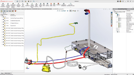
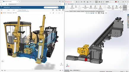
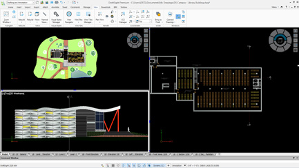
1. BIM Module
DraftSight now connects the worlds of 2D drafting and Building Information Modeling (BIM). Import RVT and IFC files to automatically generate plans, sections, elevations, and schedules.
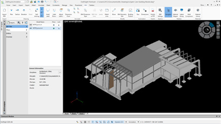
Benefit: Bridge 3D and 2D collaboration, improving accuracy and communication across project teams.
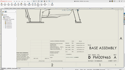
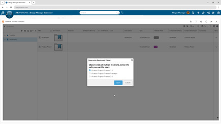
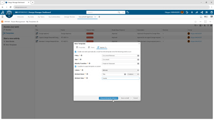
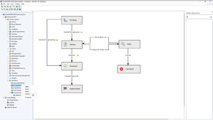
2. Sheet Set Manager on the Platform
Project documentation just got easier. The new Sheet Set Manager standardizes how drawing sheets are created, grouped, templated, and published, all from the 3DEXPERIENCE platform.
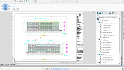
Benefit: Simplify documentation, ensure consistency, and speed up publishing workflows.
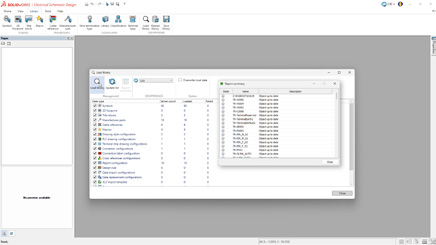
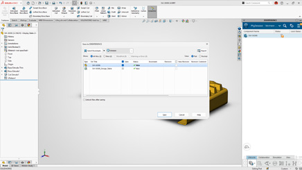
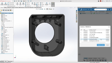
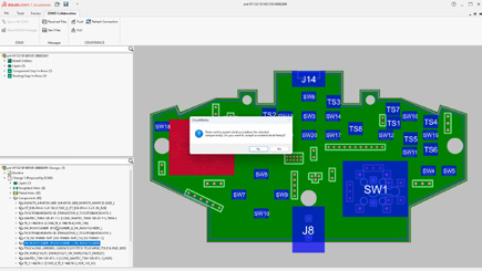
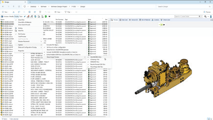
3. Batch Print Files in Collaborative Space
Save time with batch printing directly from the Collaborative Space. Process multiple DWG files at once, ensuring all team members are always working with and printing the latest version.
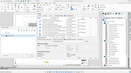
Benefit: Accelerate printing workflows and guarantee output consistency.
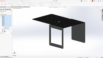
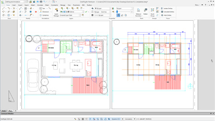
4. Float Document Windows
Multi-monitor users rejoice: DraftSight 2026 allows you to detach drawing tabs into separate windows for true multitasking. Compare and edit drawings side by side across monitors.
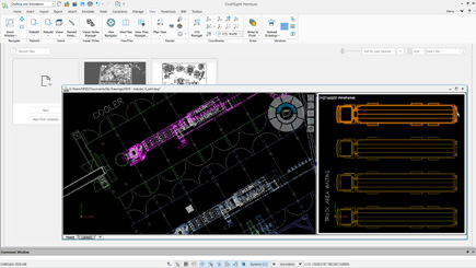
Benefit: Boost productivity by working seamlessly across multiple drawings at once.
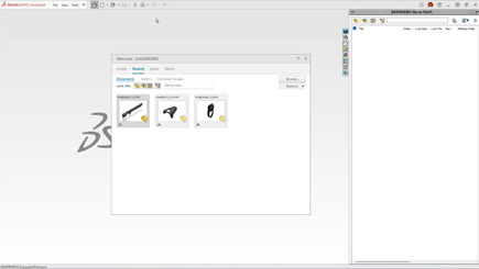
5. Centralized Start Hub
A new Start Hub streamlines how you begin every project. From one centralized location, access projects, recent files, workspace settings, and learning resources.
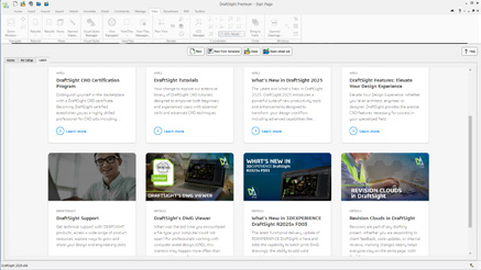
Benefit: Start faster and stay organized from the moment you launch DraftSight.
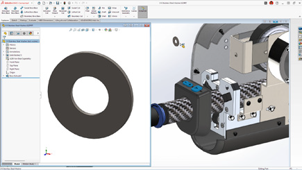
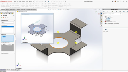
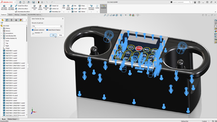
6. Resizable View Tiles in Model Space
Navigate complex models with ease by resizing and aligning multiple view tiles within model space. This makes simultaneous navigation and editing of different model areas more efficient.
Benefit: Work smarter with customizable, side-by-side model views.
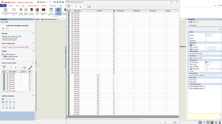
7. Field Command: Diesel Expression Support
The Field command now supports Diesel expressions, allowing dynamic text automation and inline calculations inside your drawings.
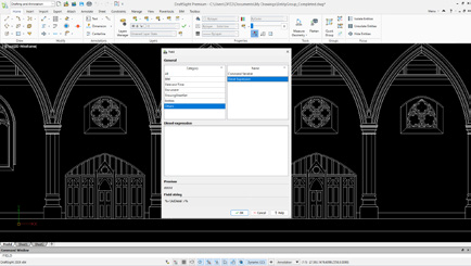
Benefit: Automate calculations and add conditional formatting directly to drawing text.
8. Improved Ribbon Tabs Content
The Ribbon interface has been cleaned up and reorganized for better usability. Enjoy faster access to commands, more intuitive layouts, and customizable workspace options.
Benefit: Streamline your drafting workflows with a more modern, intuitive UI.
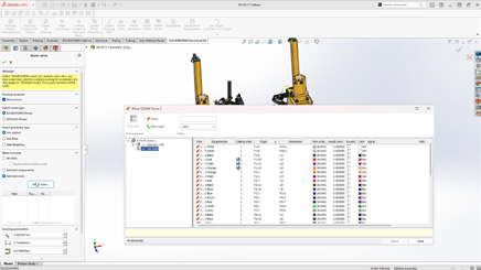
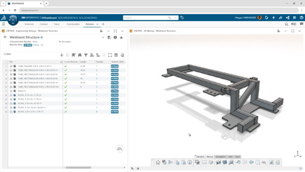
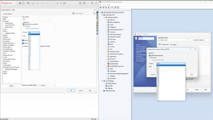
9. DATAEXTRACTION Command Improvements
Data extraction is faster and more powerful. New features include CSV headers and formula columns, reducing manual work and making it easier to integrate extracted data with external applications.
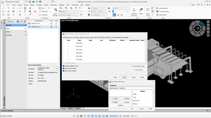
Benefit: Cut down on errors and speed up data reporting workflows.
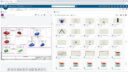
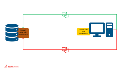
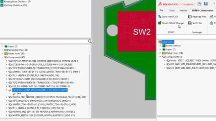
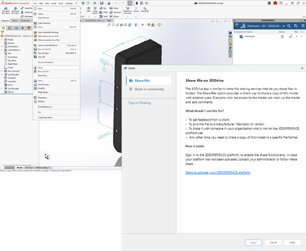
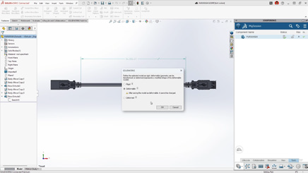
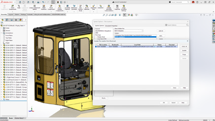
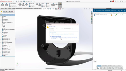
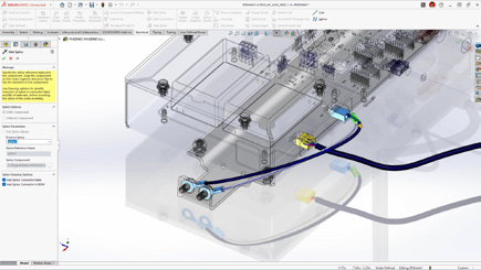
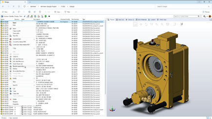
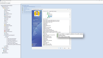
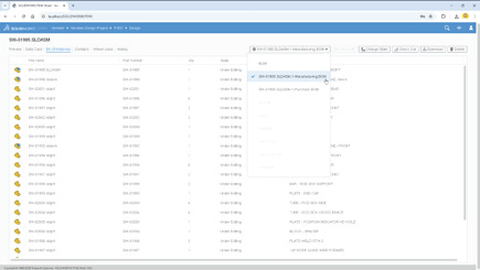
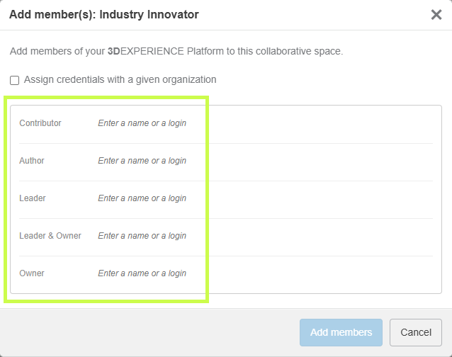
10. Files Attachable From the 3DEXPERIENCE Platform
Collaboration in the cloud takes a big step forward: DWG files stored on the 3DEXPERIENCE platform can now be attached as external references directly in DraftSight.
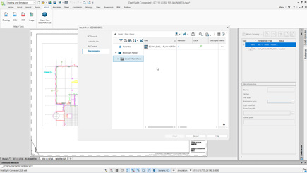
Benefit: Simplify data management and keep everyone working on the latest version of project files.
The Future of 2D CAD Starts Here
DraftSight 2026 isn’t just about drafting faster, it’s about working smarter, collaborating seamlessly, and bridging 2D with 3D workflows. From BIM integration to cloud-based collaboration and new automation tools, these enhancements set a new standard for productivity in CAD.
Want to unlock the full power of DraftSight 2026? Our experts are ready to support your team with tailored guidance, training, and workflow optimization.


Any questions? Need help? Ask one of our experts.
Whether you’re ready to get started or just have a few more questions, you can contact us toll-free: