SOLIDWORKS 2026 continues the trend of making design faster, smarter, and more connected. With AI-powered tools, streamlined workflows, and deeper collaboration features, this release is all about helping engineers and designers work more efficiently while maintaining accuracy and flexibility.
Here are the Top 10 Enhancements you need to know:
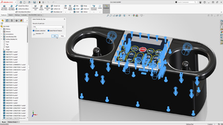
1. AI-Powered Design and Detailing
Artificial intelligence is making a real impact in everyday CAD workflows:
-
Automated drawing creation with AI-driven views, hole callouts, dimensioning, detailing, and even sheet format selection.
-
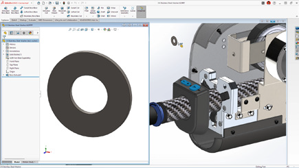
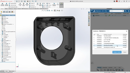
AI assembly recognition can now automatically detect and insert fastener-like components (nuts, bolts, washers), reducing repetitive tasks and improving assembly accuracy.
These enhancements deliver faster detailing and more accurate assemblies with less manual effort.
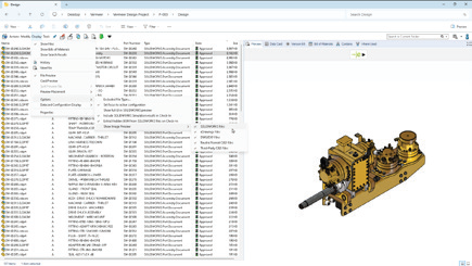
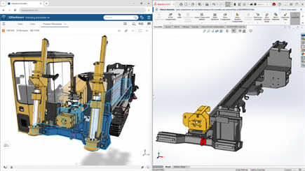
2. Large Assembly Performance
Large assemblies are now easier to manage:
-
Open massive designs faster by filtering only what you need from the 3DEXPERIENCE platform.
-
Skip rebuilds when only cosmetic changes are made.
-
Disable auto-resolve for lightweight components to improve responsiveness.
Together, these updates create smarter workflows that keep even the largest projects running smoothly.
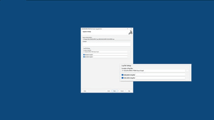
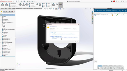
3. Improved User Experience
-
Offline mode ensures uninterrupted productivity during internet disruptions.
-
A redesigned UI highlights common commands, helping new users get up to speed quickly.
-
Command Search now includes an expanded, customizable set of keywords.
The result is a smoother learning curve and less frustration for both new and experienced users.
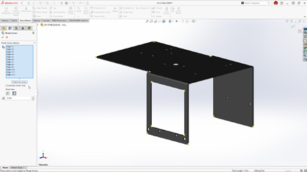
4. Streamlined Part Design
-
Define a custom start point for sheet metal base flanges.
-
Break internal corners on folded geometry.
-
Quickly create square sketch geometry in one click.
-
Track maturity changes and drawing history with Evaluated Attributes.
These improvements enable faster sketching and greater flexibility in sheet metal design.
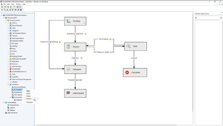
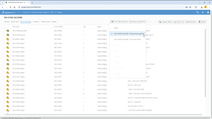
5. Collaboration & Data Management
-
Share designs directly via 3DDrive and 3DSwym.
-
Update files to the latest version on the 3DEXPERIENCE platform with a single action.
-
Access the SOLIDWORKS User Forum from within the software.
With these tools, staying in sync with your team and your data has never been easier.
6. Drawing Detailing & MBD
-
Insert Family Tables into drawings for configuration details.
-
Use magnetic lines to align not just balloons, but notes, weld symbols, and other annotations.
-
Propagate DimXpert dimensions to library features and selectively manage annotation visibility.
This gives designers more control and clarity when documenting their designs.
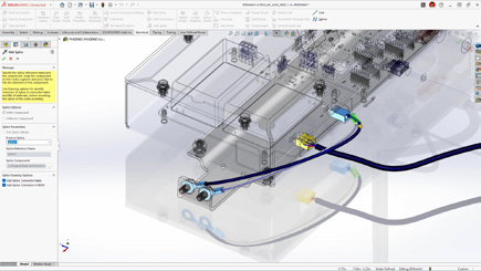
7. Routing, Electrical, and Piping
-
Combine routing BOMs across subassemblies for a clearer overall materials list.
-
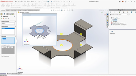
Place clips, mounts, and hangers directly in assemblies for flexible routing.
-
Visual indicators help guide splice placement in harnesses and wire bundles.
This gives designers more control and clarity when documenting their designs.
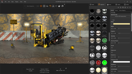
8. Rendering Enhancements
-
Control tessellation for a balance of geometry quality and performance.
-
Improved denoising in CPU mode reduces render noise in fewer passes.
-
Expanded format support with PBR materials in USDZ and glTF.
This gives designers more control and clarity when documenting their designs.
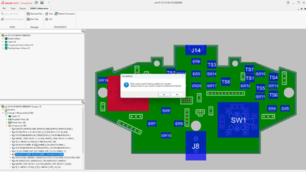
9. ECAD/MCAD Collaboration
-
Track parent/child PCB data like keep-in, keep-out, plated and non-plated holes.
-
Use CircuitWorks™ with IDX 3.0 support to review and even undo MCAD changes before final ECAD updates.
This gives designers more control and clarity when documenting their designs.
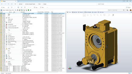
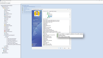
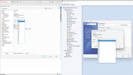
10. Import/Export
-
Simplify complex multibody parts faster by using advanced selection tools to efficiently isolate and manage bodies based on similarity or size.
-
Share assemblies saved on the 3DEXPERIENCE platform using the Export as Package option in the Share dialog box.
-
Streamline exports by choosing whether to include drawings in your package, for greater control.
This gives designers more control and clarity when documenting their designs.
Final Thoughts
With AI-powered automation, large assembly improvements, smarter part tools, and seamless collaboration, SOLIDWORKS 2026 makes it easier than ever to move from concept to finished product. Whether you’re creating complex assemblies, detailing drawings, or collaborating across disciplines, this release delivers tools to help you work smarter, faster, and with greater confidence.
Take your designs to the next level with SOLIDWORKS 2026. Contact us today to unlock smarter, faster, AI-powered engineering.


Any questions? Need help? Ask one of our experts.
Whether you’re ready to get started or just have a few more questions, you can contact us toll-free: