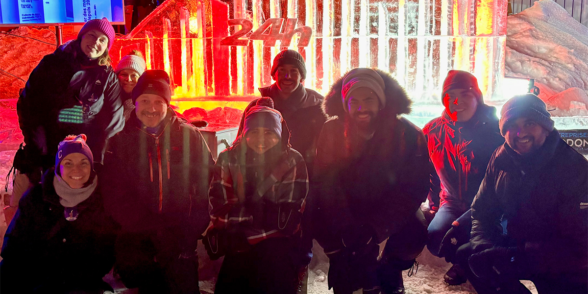
At the end of 2025, several SolidXperience employees experienced something unforgettable: our very first participation in the 24h Tremblant, a charitable event dedicated to the well-being of children.
The cause resonated with us from the very beginning. As a result, a team quickly came together. With the support of our colleagues and leadership, we pushed our limits. The energy, enthusiasm, and sense of solidarity made this experience truly exceptional.
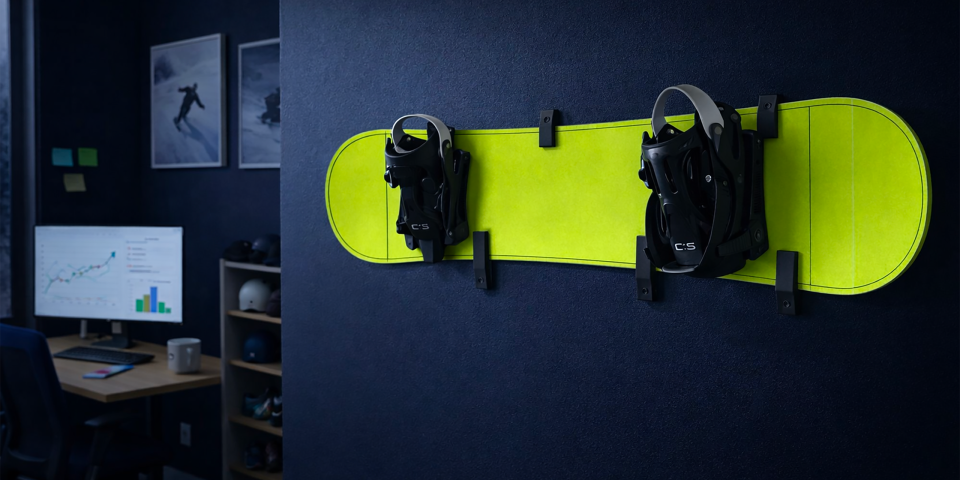
With this in mind, the Montreal additive manufacturing team wanted to make a real difference. Nearly half of its members actively participated in the event. The others supported the cause through creative initiatives, such as designing and 3D printing snowboard wall mounts, which were offered to donors.
These mounts allowed donors to transform their snowboards into unique decorative pieces. No more garage storage, their boards now proudly hang on display.
To better understand the context, before diving into our additive manufacturing project, let’s first explore what the 24h Tremblant is and why it is so inspiring.
24h Tremblant, a unique event
The 24h Tremblant is much more than a sporting challenge. It is a charitable event that combines effort, solidarity, and commitment to children supported by the Montreal Children’s Hospital Foundation. For 24 hours, teams take turns participating in activities such as running, walking, or skiing.
For our team of 3D experts, it was an opportunity to hit the slopes… or rather, the boards. Every team member is a snowboarder, which made the experience even more fun and enjoyable.
Each lap, each relay reminded us why we were there: to bring hope and support to incredibly courageous children. This year, we had the honor of sponsoring Stefano, a 15-year-old hockey enthusiast whose resilience inspired everyone. Present on the slopes, he actively participated, sharing his motivation and energy with all.
The atmosphere was festive, intense, and emotional. We laughed, encouraged each other, and pushed ourselves, all while keeping in mind that every donation and every effort helps improve the lives of young patients and their families.
Why this type of event makes an impact
In fact, events like the 24h Tremblant go far beyond a simple sporting challenge. They bring people together around a meaningful cause, generate tangible funding, and raise awareness about the realities faced by children and their families. Every participant, whether on the slopes or fundraising, contributes directly to improving the well-being of children supported by the Montreal Children’s Hospital Foundation.
In this context, for SolidXperience, this participation is part of a broader commitment. Each year, several teams also take part in the 48h Make-A-Wish, a similar event where collective energy helps transform the lives of children facing serious health challenges. Like the 24h Tremblant, these experiences raise awareness, mobilize people, and inspire action. They also strengthen team spirit, as pushing limits together for a shared cause creates lasting bonds.
The 24h Tremblant 2025 is a perfect example. By sponsoring Stefano, 16, a hockey fan and aspiring sports broadcaster, we witnessed firsthand the real impact of such an event. Despite living with two rare conditions, congenital central hypoventilation syndrome and Hirschsprung’s disease, Stefano actively participated, sharing his determination and positivity with everyone.
These events are not just fundraisers. They highlight the courage and resilience of children while giving participants the opportunity to make a meaningful difference.
The additive manufacturing project: snowboard mounts
Concretely, to support the 24h Tremblant, our additive manufacturing team wanted to contribute in a concrete and creative way. We leveraged the mechanical properties of Onyx to design and 3D print mounts capable of securely and aesthetically holding a full snowboard.
To achieve this, several steps were followed. The goal was to create a part strong enough to safely support a snowboard while keeping material costs under $10. To do so, we applied a specific 3D printing approach called “design to failure.” This method involves designing the simplest possible part, testing it, and then reinforcing only the areas that need improvement.
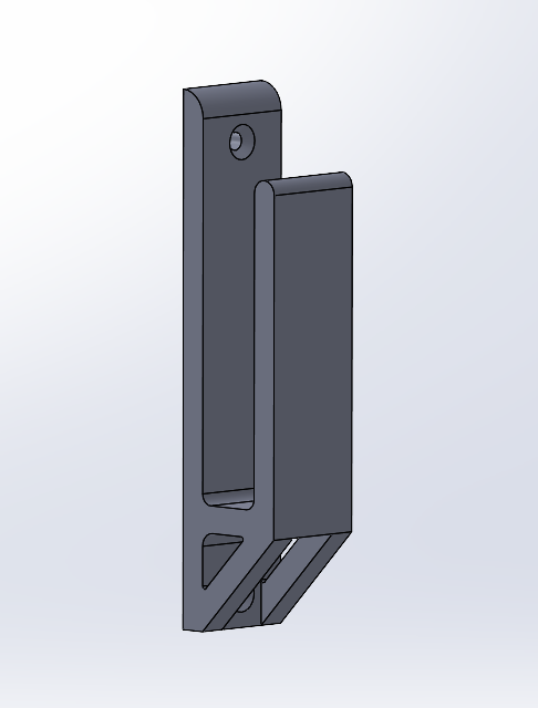
The first design tested was as follows:
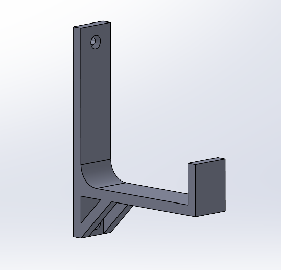
However, after initial testing, several issues were identified.
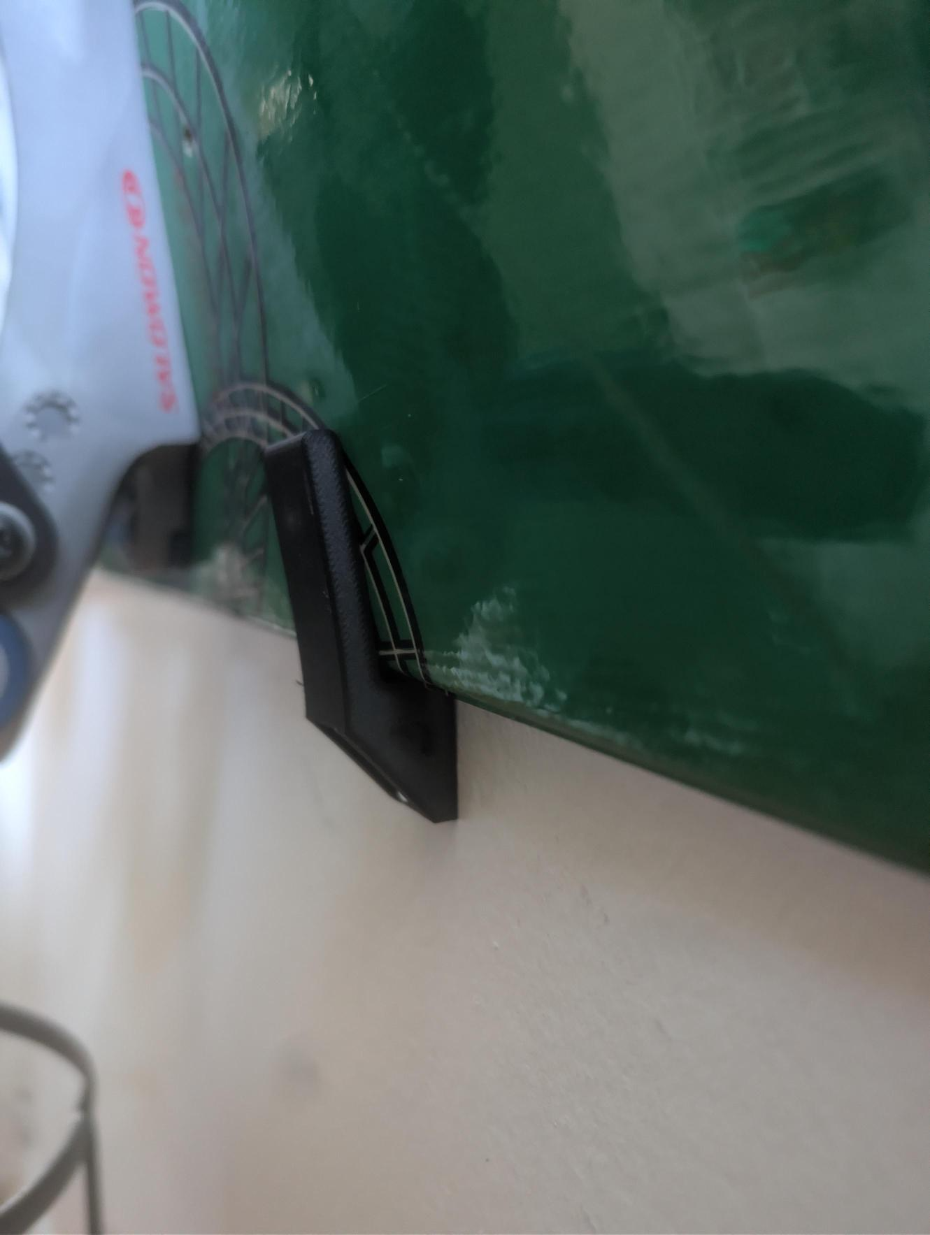
- When the snowboard was positioned close to the wall, the mount held it well. However, the bindings caused the board to tilt forward easily.
- When the snowboard was placed farther from the wall, it was stable, but the mount bent and needed reinforcement and extension to ensure safety.
Based on these observations, a second version was designed. It maintained the idea of keeping the board as close to the wall as possible to reduce the load moment. The design was modified to keep the board stable and vertical while ensuring safety.
This second version performed well in real conditions but was not yet fully secure. The front section holding the board tended to deform. As this deformation increased, the weight created more leverage, adding stress to the mount.
To address this, a third version was then designed and printed.
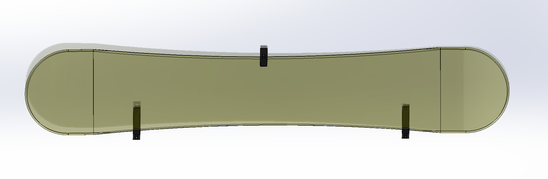
This version introduced a third hook at the top to prevent any tipping movement. This adjustment significantly reduced the load on the two wall supports. The material savings from earlier optimizations more than compensated for the addition of this third component.
In real-world conditions, the snowboard is now fully supported and can be securely mounted on the wall.
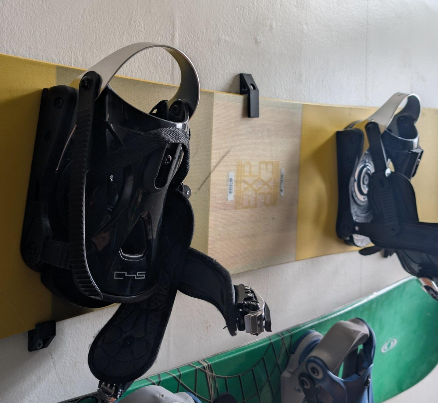
In the end, by following the “design to failure” approach, we successfully developed a snowboard wall mount with a material cost under $10. These mounts were offered to donors who met the criteria and were interested.
Producing each piece was a real pleasure, and today, every time I see my snowboard hanging on the wall, I’m reminded of the mountain, the energy of the 24h Tremblant, and the incredible experience we shared.
A project that combines passion, teamwork, and impact
Ultimately, this project demonstrated that creativity and innovation can be used to support a meaningful cause. Each 3D-printed mount combined engineering, the joy of making, and tangible support for both donors and children.
Above all, beyond the technical aspects, this experience strengthened team spirit and solidarity. Every snowboard mounted on a wall is a reminder of the energy of the 24h Tremblant and the real impact we can have when we bring our talents together for a cause that matters.
What if your next project could make a difference too? Our experts are here to help. Contact us oday.

Any questions? Need help? Ask one of our experts.
Whether you’re ready to get started or just have a few more questions, you can contact us toll-free: