FeatureWorks in SOLIDWORKS: How to Recover Design Intelligence from STEP and IGES Files Efficiently

BLOG

FeatureWorks in SOLIDWORKS: How to Recover Design Intelligence from STEP and IGES Files Efficiently

In the day-to-day work of a designer or engineering office, it’s common to receive 3D files from other CAD software. Fortunately, universal formats like STEP, IGES, or Parasolid allow for model exchange without geometry loss.


However, they present a major challenge: importing them into SOLIDWORKS strips away the feature tree, turning them into ‘dumb solids’ that are difficult to edit efficiently.


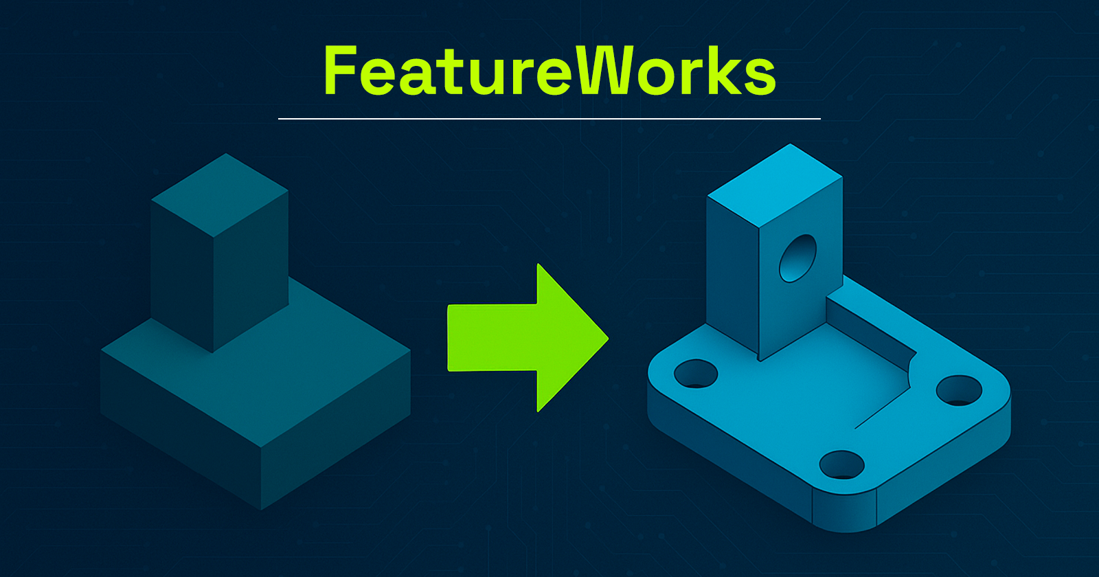
So, how can we recover the design intelligence behind a simple imported solid? The answer lies in one word: FeatureWorks.


Put simply, this SOLIDWORKS add-in enables automatic recognition of design features (holes, bosses, fillets, chamfers, etc.) from an imported body.


As a result, users can reconstruct a feature tree and thus modify, parameterize, or even automate the imported part as if the user had created it natively in SOLIDWORKS.


In this article, discover how to use FeatureWorks, its benefits, limitations, and real-world applications. It’s a powerful yet often underestimated tool for reverse engineering and collaborative CAD workflows.

What Is FeatureWorks?

Put simply, SOLIDWORKS developed FeatureWorks to bring intelligence back to 3D files that users import from other platforms. This add-in primarily functions by recognizing design features either automatically or interactively, depending on user preference


Typically, when you import a STEP, IGES, or Parasolid file, SOLIDWORKS creates a single solid body with no recognizable features. To address this, FeatureWorks analyzes the geometry to reconstruct, as accurately as possible, the original design elements: sketches, extrusions, holes, fillets, chamfers, and more.


It’s important to note that FeatureWorks is included with SOLIDWORKS Standard, Professional, and Premium. However, it’s not enabled by default. You must activate it manually through Tools > Add-ins.


Moreover, supported formats include:


  • STEP (.step, .stp)
  • IGES (.iges, .igs)
  • Parasolid (.x_t, .x_b)
  • SAT, VDAFS, and others


Consequently, FeatureWorks is especially useful for reverse engineering and working with collaborators who use other CAD platforms.

Why Use FeatureWorks?

There are several reasons why FeatureWorks is a valuable tool in a professional CAD workflow:

Save Valuable Time

First of all, manually recreating the feature tree of an imported part can be tedious. FeatureWorks offers an automatically generated base of features that you can edit or expand. Therefore, it saves a considerable amount of time, especially for simple to moderately complex parts.

Edit Parts from Other CAD Software

Once FeatureWorks recognizes the geometry, the imported part behaves like a native SOLIDWORKS model. As a result, you can make design changes without starting from scratch.

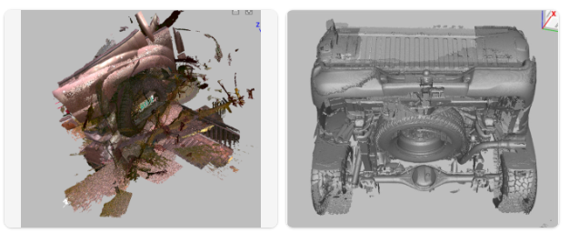
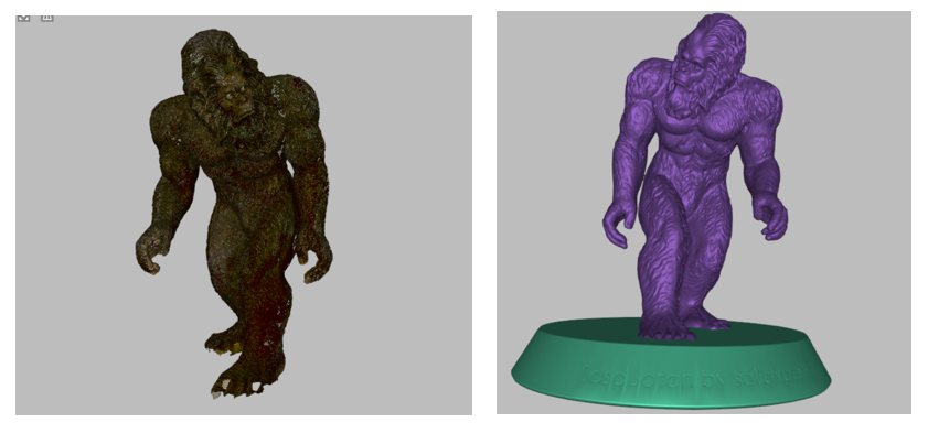
Reverse Engineering and Legacy Updates

Additionally, companies with libraries of non-parametric or scanned geometry can use FeatureWorks to restore design intent. This makes it ideal for legacy file updates and engineering change workflows.

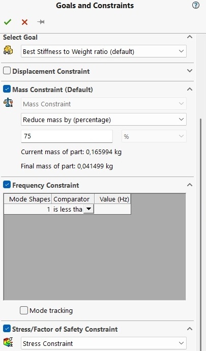
Prepare Models for DriveWorks

Finally, if you use DriveWorks to automate your designs, FeatureWorks helps convert a “dumb” STEP file into a parametric model, ready for automation.

How to Use FeatureWorks in SOLIDWORKS

Here’s a step-by-step guide to getting the most out of FeatureWorks:

1. Activate FeatureWorks

  • Go to Tools > Add-ins
  • Check FeatureWorks (and optionally, “Start Up” to load at SOLIDWORKS launch)

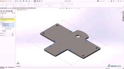
2. Import the STEP File

  • Go to File > Open, and select a STEP, IGES, or .X_T file
  • In the Import Options dialog, check Recognize Features to launch FeatureWorks automatically

3. Choose Between Automatic or Interactive Recognition

  • Automatic Recognition: SOLIDWORKS detects and reconstructs features without user input
  • Interactive Recognition: You manually select which features to recognize (slower but more accurate)

4. Explore the Options

  • Choose which types of features to recognize: holes, bosses, fillets, chamfers, etc.
  • Optionally retain a copy of the original solid body (useful for validation)

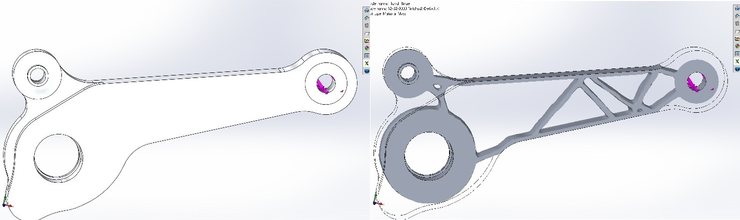
5. Result: A Partial or Full Feature Tree

Once recognition is complete, a feature tree appears in the FeatureManager Design Tree. You can edit feature parameters, add or delete features, just as you would with any SOLIDWORKS model.

Limitations and Best Practices

Incomplete or Inaccurate Recognition

Keep in mind, FeatureWorks can’t detect everything. The more complex the part (organic shapes, surfacing, molded components), the less reliable the results. Therefore, it’s best used on machined or welded parts with simple, regular geometry.


Clean the File Before Recognition

Before running FeatureWorks:


  • Remove unnecessary entities (logos, engravings, markings)
  • Simplify geometry for easier detection

Manually Verify Each Feature

After recognition, always review the results. Some dimensions or sketches may be slightly off. A quick manual validation step ensures the model is reliable for downstream tasks such as automation, simulation, or manufacturing.

Real-World Use Cases

Precision Machining Subcontractor

A machine shop regularly receives STEP files from clients. Using FeatureWorks, it automatically recognizes standard hole and milling features for seamless integration into SOLIDWORKS CAM machining operations.


Industrial Design Office

An engineering firm receives 3D files from a German supplier in IGES format. With FeatureWorks, they can modify the geometry immediatel. As a result, there’s no need to wait for the supplier to resend a modified file, boosting independence and responsiveness.


Catalog Modernization

A company wants to update old, non-parametric CAD files. To do so, it uses FeatureWorks to rebuild features and integrate them into a DriveWorks configurator for automated part generation.

FeatureWorks, A Tool to Discover or Rediscover

In conclusion, FeatureWorks is often overlooked or underutilized, yet it can be a powerful productivity tool for engineering teams working with imported files.


In just a few clicks, it transforms a static “dumb” model into an intelligent, editable, and automatable SOLIDWORKS part.


Whether you’re a designer, subcontractor, or reverse engineering specialist, take the time to explore this add-in. And if you’d like to go further, consider attending a training course or contact us with your questions.

FAQ

What’s the difference between FeatureWorks and standard STEP import?

By default, importing a STEP file into SOLIDWORKS creates a single “dumb” solid with no feature tree. This means the part lacks editable features and parametric relationships.


However, by enabling FeatureWorks, you can detect and reconstruct key features such as extrusions, holes, and fillets.


As a result, it becomes much easier to edit, parameterize, and adapt the part, just like a native SOLIDWORKS model.

Is FeatureWorks included in all SOLIDWORKS versions?

FeatureWorks comes bundled with SOLIDWORKS Standard, Professional, and Premium licenses.


However, since it’s not active by default, users must enable it manually via Tools > Add-ins before use.

How reliable is automatic feature recognition?

It depends on part complexity. FeatureWorks works best on machined parts with standard geometry.


However, for complex or organic parts, such as castings, injection-molded components, or surface-based geometry, recognition may be partial or inaccurate.


In these cases, it’s advisable to use interactive mode or reconstruct features manually.

Can FeatureWorks be used on STEP assemblies?

No.


Important to note: FeatureWorks only works with individual parts. If you’re dealing with a STEP assembly, you’ll need to open each component separately and apply FeatureWorks to each one.

Can FeatureWorks detect constraints or sketch relations?

No, it does not. While FeatureWorks can recognize solid features, it does not recreate sketch constraints or parametric relations.


Therefore, once recognition is complete, it’s advisable to manually review and add necessary constraints.

Can FeatureWorks be used with DriveWorks?

Yes and it’s an excellent use case!


Once a part is imported and recognized using FeatureWorks, it can be parameterized and automated using DriveWorks.


As a result, this turns imported geometry into reusable components for product configurators.

What file formats are supported by FeatureWorks?

FeatureWorks supports the following:

  • STEP (.stp, .step)

  • IGES (.igs, .iges)

  • Parasolid (.x_t, .x_b)

  • SAT, VDAFS


However, to ensure proper recognition, the file must contain a valid solid body. Without it, FeatureWorks cannot accurately detect or reconstruct design features.


Alain

Alain Provost

Senior Technical Sales Executive

X_green_halo

Any questions? Need help? Ask one of our experts.

Whether you’re ready to get started or just have a few more questions, you can contact us toll-free:

    Best 3D Scanning Tools for Any Environment

    BLOG

    Best 3D Scanning Tools for Any Environment

    3D scanning technology has become increasingly accessible and versatile, allowing professionals to capture accurate digital models of objects in nearly any environment. Whether you’re scanning indoors in a controlled space or outdoors in unpredictable conditions, understanding how your tools respond to these settings is key. To better illustrate this distinction, the Artec Ray and Artec Leo are two scanners designed for different strengths the Ray excels at long-range, high-accuracy scanning, while the Leo offers handheld mobility and real-time feedback. As a result, when paired together or used separately, they can tackle a wide variety of scanning tasks with the right preparation.


    How to Optimize Outdoor 3D Scans with the Artec Leo Handheld Scanner

    The Artec Leo is a versatile handheld 3D scanner that can handle a wide range of outdoor scanning tasks, including vehicles and textured objects like statues. While it may require additional preparation for reflective surfaces, its mobility and real-time feedback make it a powerful tool for capturing complex shapes. To support this, here are some of the Leo’s key technical capabilities:


    ·        3D point accuracy: Up to 0.1 mm

    ·        Scanning range: 0.4 to 10 meters

    ·        3D resolution: Up to 0.2 mm

    ·        3D reconstruction rate: Up to 80 frames per second (FPS)

    ·        Volume capture zone: 160,000 cm³

    ·        Display: Built-in touchscreen panel

    ·        Processing: Onboard real-time 3D data processing


    Moreover, by understanding these capabilities and adapting the scanning approach like adding reference points on reflective surfaces you can optimize results whether scanning vehicles or textured statues.


    Improving Scan Accuracy with Reference Points and Cleanup Tools

    When working on larger projects, scan data can quickly become overwhelming. Especially when imported into Artec Studio. Often, the scans initially appear as a chaotic mess, with no clear orientation. For instance, a great example is our practice scan of a truck using the Artec Leo. This scan was done in peak sunlight, which made the truck’s reflective sides more difficult to capture accurately. To help with alignment, we placed small magnets on the sides of the truck as reference points. Thanks to Artec Studio’s user-friendly cleanup tools, the process of aligning parts becomes much smoother, reducing both time and stress. This practice emphasizes the importance of capturing high-quality and thorough scans from the start. Taking a bit more care during scanning can significantly speed up post-processing, making it easier for both you and your computer.


    Truck by scanned by a 3D scanner

    When to Use the Artec Ray for Outdoor Scanning

    The Artec Ray 3D scanner excels in outdoor scanning projects that demand precision over large areas. Its metrology-grade accuracy and long-range capabilities make it ideal for capturing detailed scans of buildings, infrastructure, and large objects. Key technical specifications include:


    • 3D point accuracy:
      • 1.9 mm at 10 meters
      • 2.9 mm at 20 meters
      • 5.3 mm at 40 meters
    • Angular accuracy: 0.87 mm at 10 meters (18 arcseconds)
    • Range accuracy: 1.0 mm + 10 ppm
    • Range noise: 0.4 mm at 10 meters, 0.5 mm at 20 meters

    While outdoor conditions such as bright sunlight or uneven terrain may pose challenges, using a stable tripod and scanning during optimal lighting can help ensure the Ray produces highly detailed and reliable scans with minimal post-processing.


    Using Artec Leo and Ray for Advanced Outdoor 3D Scanning Workflows

    When working outdoors, leveraging both the Artec Leo and Artec Ray 3D scanners allows for a more versatile and efficient scanning process. The Ray handles broad, large-scale captures, creating a detailed foundation that ensures no major features are missed. Meanwhile, the Leo excels at filling in smaller or more complex areas that require flexibility and maneuverability. By integrating data from both devices, you can achieve a highly detailed and complete 3D model. Planning your scanning sequence thoughtfully starting with the Ray and following up with the Leo streamlines data alignment and reduces overall processing time making the workflow smoother and more productive.


    Why the Artec Leo Excels in Small and Complex Indoor Spaces

    Indoors, the Artec Leo’s handheld design and real-time processing offer significant advantages for scanning smaller spaces or detailed objects. In addition, its portability allows operators to move easily around furniture, fixtures, or machinery, capturing intricate details that stationary scanners might miss. Additionally, the built-in touchscreen and immediate feedback help ensure scan quality on the spot, reducing the need for reshoots. This makes the Leo especially useful for tasks like heritage preservation, quality control, and product design within confined or complex indoor environments.


    Real-World Scan: Digitizing a Trade Show Display with Artec Leo

    During our last trade show, there was a vendor Gorilla Circuits that had a fun Sasquatch podium piece which they allowed us to scan with the Leo so we could demonstrate just how easy it is to take an object and digitize it using the Artec Leo process. The scan data was then 3D printed on the Raise3D Pro3 and the Markforged Mark Two Desktop 3D Printer.


    In fact, it really only took one primary scan and two small scans to fill in the missing information. Artec Fusion software was able to fill in any missing sections with extreme accuracy, referencing the scan data to create a watertight file. The original Sasquatch was just under two meters tall, and the 3D printed models were 180 mm tall for the display case.

    Sasquatch scanned by Artec LEO

    Why the Artec Ray Is Ideal for Large Indoor Environments

    The Artec Ray is well suited for mapping large indoor environments such as production floors, warehouses, or empty buildings. Similarly, its long-range scanning capability allows for fast and accurate capture of expansive areas, which is essential for planning HVAC installations, scaffolding setups, or construction projects. By providing precise spatial data from floor to ceiling, the Ray helps engineers and architects create reliable models to support design and implementation. The scanner’s stability and accuracy reduce the time spent on manual measurements, streamlining workflows in large-scale indoor projects.


    From Insight to Action: Match the Scanner to the Job

    Ultimately, whether you are scanning a compact object in a cluttered room or mapping out an entire facility, knowing how to get the most out of your equipment is key. The Artec Leo and Ray each bring unique strengths to the table, and when used together, they can cover nearly every scanning scenario both inside and out. Success comes from understanding your environment, choosing the right tool for the job, and preparing your scan area thoughtfully.


    If you’re ready to take the next step, contact us for full access to product demos, hands-on training, and expert guidance to help you get started with confidence.


    Richard Forcier

    Solutions Specialist – Additive Manufacturing & 3D Scanning

    X_green_halo

    Any questions? Need help? Ask one of our experts.

    Whether you’re ready to get started or just have a few more questions, you can contact us toll-free:

      How to Reduce Costs in Your Designs with Topology Optimization in SOLIDWORKS

      BLOG

      How to Reduce Costs in Your Designs with Topology Optimization in SOLIDWORKS

      In design and engineering, striking the right balance between performance, material usage, and cost is crucial. Whether you’re working on parts for an automotive application, aerospace components, or even consumer products, the goal is often to create designs that perform optimally while using as little material as possible. This is where topology optimization in SOLIDWORKS comes into play. It’s a technique that helps you determine the best way to distribute material across your design to meet your performance goals. Various tools from Dassault Systèmes, such as SOLIDWORKS Simulation Premium and SOLIDWORKS Simulation Professional, can help guide you in making your parts more efficient and cost-effective. SIMULIA, a brand of other solutions from Dassault Systèmes, also supports topology optimization for more advanced simulation needs.


      In this tech tip, we’ll walk through what topology optimization is and how it works. We’ll also explore how it can help you design lighter, stronger, and more cost-efficient parts using a variety of simulation tools.

      What Is Topology Optimization?

      At its core, topology optimization is all about optimizing the material layout of a part to achieve specific performance goals. Imagine it like sculpting a piece of clay. Removing unnecessary material and shaping the remaining material in a way that ensures the part performs as required, without excess weight or material.


      Although the term “topology” might seem technical, it really just refers to how material is arranged within a given design space. In simple terms, topology optimization in SOLIDWORKS helps you design parts that are as efficient as possible by strategically placing material where it’s needed most. The end result is a part that’s lighter, more durable, and better suited to its intended function.

      Before and after topology optimization

      Key Objectives and Constraints of Topology Optimization

      When you set up a topology optimization study in simulation software, you’re essentially telling the software what you want to achieve. Some of the key objectives or constraints typically include:


      • Stress: Ensuring that the part can handle forces without failure. The goal is to have the material placed exactly where it’s needed to support the stresses applied to the part.
      • Factor of Safety: This is a cushion of extra strength that guarantees the part can withstand unforeseen or extreme conditions, minimizing the risk of failure.
      • Frequency: For parts exposed to vibrations, such as frames or supports, optimizing for frequency is essential. It helps ensure the part avoids resonating at certain frequencies, which could otherwise lead to failure.
      • Manufacturability: No matter how efficient a design is, it still has to be manufacturable. Simulation tools factor in real-world constraints during the design process. This ensures the final design can be produced using methods like CNC machining, additive manufacturing, or injection molding.

      Goals and constraints in a Topology Optimization in SOLIDWORKS Simulation

      How Does Topology Optimization Work?

      The process of running a topology optimization in a SOLIDWORKS study is straightforward. This holds true whether you’re using SOLIDWORKS Simulation Premium, SOLIDWORKS Simulation Professional, or other solutions from Dassault Systèmes. Here’s a simplified step-by-step guide:


      1. Define the Design Space: First, you outline the area in which material can be placed or removed. This is the region where you will optimize the design.
      2. Apply Loads and Fixtures: You then define the forces, pressures, and any constraints the part will experience in the real world. For instance, you might specify areas where the part is fixed or under load.
      3. Set Your Optimization Goals: Next, you specify what you want to achieve with the optimization. Are you focusing on reducing weight? Improving strength? Or perhaps increasing the safety margin? Simulation tools let you set multiple objectives at once.
      4. Run the Simulation: Once all parameters are in place, the software runs the simulation. It gradually removes material from areas that don’t contribute significantly to performance, leaving behind only the necessary structure.
      5. Evaluate and Refine the Design: After the optimization process is complete, you receive a design that meets your performance requirements. You can then further refine it to ensure it fits your specific manufacturing processes.

      Why Should You Use Topology Optimization?

      Here are some compelling reasons to incorporate topology optimization in SOLIDWORKS into your design process:


      1. Material Efficiency: By using topology optimization, you ensure that you’re only using as much material as necessary, creating parts that are lighter and more efficient. This is particularly important in industries like aerospace or automotive, where every gram saved can lead to better performance.
      2. Cost Reduction: Using less material translates to direct cost savings. Topology optimization can help lower both material costs and manufacturing expenses, as lighter parts are often easier and less expensive to produce.
      3. Enhanced Performance: By strategically placing material where it’s needed most, topology optimization ensures that your design is as strong as possible without adding extra weight or material. This results in better-performing parts overall.
      4. Faster Design Process: Instead of manually exploring different design options, simulation tools allow you to quickly run multiple simulations and find the best solution. This saves you time and effort during the design phase.
      5. Real-World Manufacturability: Simulation tools don’t just optimize for performance. They also keep manufacturability in mind. Whether you’re using 3D printing, traditional machining, or injection molding, the software ensures your optimized design can be made with real-world methods.

      Real-World Applications

      Here are a few examples of industries that benefit from topology optimization in SOLIDWORKS include:


      • Aerospace: Lighter, optimized parts are crucial for improving fuel efficiency and reducing the weight of aircraft. Engineers use topology optimization to design components that meet both performance and weight goals.
      • Automotive: In the automotive industry, optimizing parts for weight without compromising on safety and durability is key to reducing fuel consumption and production costs.
      • Consumer Products: From smartphones to sporting equipment, topology optimization helps designers create products that are both strong and lightweight, offering improved performance and better user experience.
      • Medical Devices: In medical fields, especially with implants or prosthetics, topology optimization can help create designs that are comfortable, effective, and use less material without compromising performance.

      Progression of topology optimization in SOLIDWORKS

      This nonlinear brake pedal example shows the progression of topology optimization as it attempts to maximize the stiffness while reducing the volume by 50% during 31 design cycles. Source: https://www.3ds.com/fileadmin/PRODUCTS-SERVICES/SIMULIA/RESOURCES/SIMULIA-Abaqus-Topology-Optimization-Module.pdf

      A Brief Look at Generative Design

      While topology optimization is a reliable and proven method for optimizing designs, generative design is a more recent approach that can take things a step further. Generative design uses powerful algorithms to create multiple design alternatives based on a set of input parameters. It not only optimizes material layout but also explores entirely new shapes and forms that might not be immediately apparent.


      For example, generative design might suggest unusual geometries or structures, often resulting in designs that are lighter and more efficient than what traditional design approaches might produce. This is especially useful when working with complex shapes or materials that benefit from additive manufacturing (3D printing).


      While generative design is a cutting-edge technology, topology optimization remains a great starting point. It allows for the creation of structurally optimized components that meet performance goals while adhering to manufacturing constraints.

      Engineering the Future: Unlock Efficiency and Savings with Topology Optimization in SOLIDWORKS

      Whether you’re using SOLIDWORKS Simulation Premium, SOLIDWORKS Simulation Professional, or other advanced simulation tools, topology optimization can transform your design process. It’s a game-changer for creating more efficient and cost-effective parts. By optimizing material usage based on specific design goals, you can create parts that perform better while using less material. Whether you’re looking to reduce weight, improve strength, or save on manufacturing costs, topology optimization can help you achieve all of these objectives.


      If you’re interested in exploring even more innovative possibilities, generative design offers a fascinating, forward-thinking approach. It builds on the foundation of optimization to explore new and creative solutions.


      By integrating topology optimization into your design process, you’ll not only improve your product’s performance but also save time and money. This leads to designs that are both more efficient and manufacturing-ready.


      This series of short videos shows you how to set up a topology optimization study using SOLIDWORKS Simulation to help you reach your goals. Want to go further? Contact our experts to get training or learn more about SOLIDWORKS Simulation.


      Chung Ping Lu, eng.

      Chung Ping Lu, eng.

      Senior Technical Representative

      X_green_halo

      Any questions? Need help? Ask one of our experts.

      Whether you’re ready to get started or just have a few more questions, you can contact us toll-free:

        How to Scale your Business with the Artec Ray II 3D Scanner

        BLOG

        How to scale your business with the Artec Ray II 3D scanner

        Unlocking growth across industries with the Artec Ray II 3D scanner

        In today’s competitive landscape, scaling your business isn’t just about taking on more it’s about doing it more efficiently, faster, and with bigger margins that benefit you. The Artec Ray II 3D Scanner, a long-range LiDAR 3D scanner from xAI, is revolutionizing how industries operate by delivering precision, speed, and efficiency from up to 130 meters away. Whether you’re crafting industrial equipment, optimizing your plant layouts, designing aerospace components, shaping infrastructure, or solving forensic puzzles, this tool can transform your workflow. Let’s explore how the Artec Ray II 3D scanner boosts your profitability in manufacturing industrial equipment, floor plan measurements in manufacturing plants, aerospace, civil engineering and architecture, and forensics focusing on its ability to cut time, minimize mistakes, and supercharge efficiency.


        Artec Ray II 3D scanner


        Manufacturing industrial equipment: Precision meets profit with the Ray II

        For businesses manufacturing industrial equipment think heavy machinery, turbines, or pumps scaling profitably means delivering faster without compromising quality. The Artec Ray II 3D Scanner captures up to 2 million points per second, creating detailed 3D models with metrology-grade accuracy in minutes, not hours. This speed slashes you’re prototyping and production timelines, letting you ship sooner and invoice faster. In addition, fewer delays mean higher throughput, bigger margins, and the ability to take on more business that grows your bottom line.


        The real margin booster? Fewer mistakes. With high-resolution scans and scan-to-CAD integration via Artec Studio, you can reverse engineer parts or spot design flaws early, avoiding costly rework. Its portability also cuts time by bringing scanning onsite no need to ship components or halt your production. By reducing manual measurement errors and accelerating workflows, the Ray II drives efficiency, letting you take on complex, high-value projects while keeping overhead low. Scale your output, not your expenses.


        Measuring floor plans in manufacturing plants: Efficiency that pays

        Scaling a manufacturing plant hinges on optimizing space and workflows every square foot count toward your bottom line. Measuring floor plans manually is slow and error-prone, eating into margins with wasted time and miscalculations. The Artec Ray II 3D scanner changes that, mapping entire facilities with millimeter accuracy in hours, thanks to its long-range capability and top-tier angular precision.


        This speed cuts planning time dramatically think days turned into hours freeing you to reconfigure layouts or plan expansions without downtime. Accurate digital twins reduce mistakes like equipment misplacement or workflow bottlenecks, saving on costly fixes that could slow you down. Efficiency soars as you simulate changes virtually, ensuring every adjustment maximizes productivity. For growing businesses like yours, this means higher margins through faster turnarounds and leaner operations more output, less waste, and the ability to scale capacity profitably.


        3D scanning floor plans in a manufacture


        Aerospace: Soaring margins with 3D scanning precision

        In aerospace, where precision is non-negotiable, scaling profitably requires balancing speed with flawless execution something you likely demand every day. The Artec Ray II 3D scanner excels, scanning massive objects like aircraft fuselages with submillimeter accuracy in hours instead of days. This rapid turnaround cuts your inspection and design validation time, letting you meet tight deadlines and bill clients sooner boosting your cash flow and margins.


        Its precision eliminates errors that could ground a project think misaligned components or undetected wear. Fewer mistakes mean less rework, saving you on labor and materials while keeping schedules intact. Efficiency spikes as engineers analyze high-quality 3D data faster, iterating designs with agility. Pair it with other Artec scanners for hybrid workflows, and you’ve got a streamlined process that scales your output without scaling your costs. Secure more contracts, deliver on time, and watch your margins climb.


        Civil engineering and architecture: building profits smarter

        As for civil engineering and architecture, scaling means delivering standout projects without budget overruns a goal you’re probably chasing. The Artec Ray II 3D scanner makes it happen, scanning bridges, tunnels, or skyscrapers with world-class precision in a fraction of the time traditional surveys take. Faster data collection hours instead of days—cuts your labor costs and keeps your projects on track, directly enhancing margins.


        Accuracy is the mistake-killer here. Detailed 3D models prevent errors in design or construction like misjudged supports or clashing systems saving you thousands in rework. Efficiency shines through digital twins, streamlining collaboration and planning. Need to renovate a historic site or layout a new infrastructure project? The Ray II’s portability and remote scanning (via the Artec Remote App) eliminate delays from hard-to-reach areas. By slashing timelines and boosting precision, you can take on bigger jobs, deliver superior results, and grow profitably.


        Forensics: Solving cases with clarity

        In forensics, every detail matters whether you’re reconstructing a crime scene, analyzing evidence, or presenting findings in court. Scaling your forensic business means handling more cases with greater reliability, and the Artec Ray II 3D scanner is built for it. Its ability to rapidly scan large scenes like a vehicle or building with submillimeter accuracy creates tamper-proof 3D records that stand up to scrutiny.


        The advantage lies in its efficiency and detail. Traditional methods like photography or tape measures can’t match the Ray II’s 3D scanner speed or depth. A single scan captures everything from tire tracks to structural damage, preserving evidence in a digital format that’s easy to analyze or share perfect for your needs. For growing forensic firms, this means faster case turnarounds and a reputation for cutting-edge work. Plus, the scanner’s lightweight design and remote capabilities let investigators work in tight or hazardous spaces without compromise. Scaling here isn’t just about volume it’s about credibility, and the Ray II 3D scanning system delivers both for you.


        Forensics 3D scanning


        Why the Artec Ray II is your  margin multiplier?

        Across these industries, the Artec Ray II 3D scanner isn’t just a scanner it’s your profit engine. Not only does its portability cuts time by bringing precision onsite, no logistics required, but is also able to capture millions of points quickly slashes your project timelines, letting you deliver more with less effort. Furthermore, its accuracy eliminates costly mistakes, from design flaws to layout errors, preserving your budget. And, its versatility, syncing with tools like Artec Studio, tailors efficiency to your needs.


        Scaling profitably means trimming fat while boosting value. The Ray II 3D scanner reduces your labor costs by automating slow manual tasks. It minimizes rework by catching issues early. It enhances your margins by enabling faster, higher-quality deliverables letting you command premium rates or secure bigger deals. From manufacturing to architecture, this tool future-proofs your business with data-rich 3D models that drive smarter decisions. In 2025, it’s your edge for cutting time, reducing errors, and scaling efficiently.


        Ready to boost your margins?

        The Artec Ray II 3D scanner is your key to growth. Dive in, and watch your business thrive. Curious about how 3D scanning could fit into your work? Contact our experts and they will help you with any request you may have.


        James O’ Farrell

        Head of Additive Manufacturing

        X_green_halo

        Any questions? Need help? Ask one of our experts.

        Whether you’re ready to get started or just have a few more questions, you can contact us toll-free:

          SWOOD: The Ideal Woodworking Design Software

          BLOG

          SWOOD: The ideal woodworking design software

          SOLIDWORKS is the gold standard for 3D CAD, used in many industries, including mechanical engineering and product design. However, as a timber design software, it has certain limitations in terms of 3D timber modelling and timber production optimisation. However, when it comes to wood design and manufacturing, there are some limitations, making the process less efficient and more error-prone.

          This is where SWOOD, a supplement specially designed for cabinetry, carpentry, interior design, and even the current trend VanLife! comes into play. This solution brings features specific to the wood trade that perfectly complement SOLIDWORKS, facilitating the transition from design to production. In this article, we’ll explore in detail why SWOOD is a strategic choice for optimizing your wood designs in SOLIDWORKS, highlighting its benefits, features, and impact on the productivity and profitability of companies in the industry.

          blog pic 62

          SOLIDWORKS: A powerful but generalist foundation

          SOLIDWORKS is widely recognized for its flexibility in mechanical and industrial design. Key strengths include:

          • An intuitive, parametric 3D environment facilitating the design of complex parts and assemblies
          • Extensive integration with analysis and simulation tools (material strength, airflow, kinematics, etc.)
          • Advanced management of assemblies and drawings for production
          • A rich ecosystem of plugins and third-party solutions to extend its capabilities according to the user’s needs

          However, SOLIDWORKS remains a general-purpose software. In the context of wood design, several limitations are felt:

          • Lack of native management of panels and wood-based materials (MDF, laminate, plywood, etc.)
          • Complexity of creating specific connections (grooves, mortise and tenons, lamellos, etc.)
          • Lack of bookcases suitable for hardware components commonly used in layout and millwork
          • Need to develop macros or scripts to automate certain recurring tasks. It is in this context that SWOOD brings considerable added value.

          Why is SWOOD an ideal add-inn for wood design?

          SWOOD is a set of modules developed specifically for the wood sector, offering a complete solution tailored to the needs of carpenters and furniture manufacturers. Unlike other generalist software, SWOOD stands out for its dedicated approach, integrating a wood CAD plugin that automates the design and assembly of panels, hardware and specific machining. Through woodworking automation, SWOOD helps significantly reduce errors, optimize material usage, and speed up the transition from design to manufacturing, making the process smoother, more cost-effective, and designed to integrate seamlessly with SOLIDWORKS. In short, it offers dedicated tools that simplify the design and production of wooden furniture, fixtures and structures.

          The main modules of SWOOD:

          SWOOD Design:

          • Advanced panel management, with automated creation of cutouts and assemblies
          • Smart libraries Generation of detailed bills of hardware and standard elements (hinges, slidesmaterials to optimize purchasing and production, fasteners, etcalong with comprehensive SWOOD documentation tools for better project management.)
          • Generation of detailed bills of materials to optimize purchasing and production
          • Automation of wood assemblies and constraints

          SWOOD CAM:

          • Machining module for generating CNC programs adapted to machines in the woodworking sector
          • Automatic recognition of drilling and machining
          • Machining simulation to detect possible errors before production
          • Support for 3, 4 and 5 axis machines

          SWOOD Nesting:

          • Optimization of the placement of parts on the panels to limit falls and reduce costs
          • Advanced management of formats and machining priorities
          • Management of facades and grouping of items by blank slabs

          SWOOD Center

          Product configurator for the wood industry. The SWOOD Center is an advanced solution for configuring tailor-made products in the world of wood and fittings. Integrated with SOLIDWORKS, this configurator optimizes process design, production, and automation.

          Why choose SWOOD Center?

          1. Advanced customization

          • Parametric configuration of furniture and layouts
          • Managing Product Variants and Options
          • Dynamic visualization of changes

          2. Workflow automation

          • Automatic generation of production files (drawings, bills of materials, CNC programs)
          • Integration with SWOOD Design and SWOOD CAM
          • Material optimization and error reduction

          3. Time saving and efficiency

          • Reduced design time
          • Simplifying processes for technical and business teams
          • Improved responsiveness to customer requests

          An ideal solution for manufacturers and fitters

          Thanks to SWOOD Center, wood professionals can standardize their designs while offering tailor-made solutions to their customers. This configurator is particularly suitable for carpenters, fitters, kitchen designers and furniture manufacturers who want to modernize their design and manufacturing process.

          By integrating SWOOD Center into your workflow, you can accelerate your product time-to-market while ensuring a reliable and accurate design.

          The benefits of an integrated woodworking software

          Using SOLIDWORKS and SWOOD together provides many benefits, including:

          • Time saving: Automation of repetitive tasks such as inserting fasteners, managing panels and exporting files for production
          • Reduction of errors: Consideration of the specificities of the wood from the design stage, thus limiting corrections during the manufacturing phase
          • Full shop floor compatibility: Ability to generate CNC files that can be used directly by machine tools
          • Cost optimization: Less scrap, better management of raw materials and reduction of production times
          • Improved collaboration: Easier integration with other departments in the company, including production and purchasing teams

          These advantages allow manufacturers to gain in competitiveness while guaranteeing optimal quality to their customers.

          In addition, with SWOOD, companies can streamline their design processes, reduce human error, and maximize shop floor efficiency.

          SWOOD Testimonial: Reviews and case studies

          Many carpentry and layout companies have successfully adopted SWOOD. Here is a concrete example:

          Groupe Beaubois faced the challenge of improving the efficiency of its project and streamlining its operations. To achieve this, he needed to embrace technological advancements and integrate automation and robotization into his factory. However, he quickly realized that his design software played a vital role in facilitating the flow of information on his equipment. That’s when he discovered the SWOOD solution, which was specially designed for the wood industry.


          Return on investment and development prospects

          Investing in SWOOD represents an initial cost that is quickly amortized thanks to productivity gains. Here are a few things to consider:

          • Learning time: Quick training is often enough to master the basics of the software
          • Material savings: Better cutting management and reduced errors
          • Valuation of internal skills: Designers gain autonomy and efficiency

          In the future, the integration of SWOOD with technologies like artificial intelligence and 3D printing could further improve the performance of the industry.

          Now, it’s your turn to take control of your production with SWOOD

          If your processes are disconnected and your work seems to be in silos! Whether you’re switching from one solution to another to get your production up and running, the SOLIDWORKS + SWOOD combination is a powerful, comprehensive solution that’s perfect for you. It helps optimize design, improve accuracy, and increase efficiency, while reducing costs and errors. By integrating SWOOD into your workflow, you ensure better control of your production and increased competitiveness in the market.

          If you’d like to learn more about SWOOD and its integration with SOLIDWORKS, request a demo of SWOOD for wood design today and learn how to optimize your woodworking and layout projects! Contact us or request a demo today!


          Alain Provost

          Senior Technical sales executive

          X_green_halo

          Any questions? Need help? Ask one of our experts.

          Whether you’re ready to get started or just have a few more questions, you can contact us toll-free:

            Eiger.io: Unlocking the Full Potential of Industrial 3D Printing

            BLOG

            Eiger.io: Unlocking the Full Potential of Industrial 3D Printing

            Imagine having a manufacturing assistant that not only slices your parts but also optimizes strength, reduces material waste, and seamlessly integrates into your workflow. Whether you’re an engineer designing custom aerospace brackets, a manufacturer producing strong, lightweight end-use parts, or an operations manager overseeing a fleet of industrial 3D printers, Eiger.io is designed to work for you. More than just a slicer, Eiger.io is a complete industrial 3D printing platform. It offers advanced simulation, real-time analytics, and an open API that allows you to automate and optimize production.


            Let’s dive into how you can take full advantage of Eiger’s industrial 3D printing capabilities.


            1. The Slicer: More Than Just G-Code for Industrial 3D Printing

            If you’ve ever struggled with getting the perfect balance of strength and weight in your industrial 3D-printed parts, you’ll love what Eiger can do. Unlike generic slicers, Eiger is built specifically for Markforged’s high-performance industrial 3D printers, giving you intelligent control over fiber reinforcement and part strength.


            Real-World Example: Reinforcing an Industrial Robotic Arm Bracket

            Say you’re designing a robotic arm bracket for an industrial 3D printing application that needs to be both strong and lightweight. With traditional 3D printing, you might print it solid for strength, making it heavy and material-intensive. But with Eiger’s fiber reinforcement controls, you can strategically add carbon fiber layers along the bracket’s stress points, matching the strength of aluminum while keeping the weight low.


            • Continuous Fiber Reinforcement: Place carbon fiber, Kevlar, or fiberglass in key areas for superior strength.
            • Smart Layering: Adjust fiber placement per layer to reduce weight without compromising durability.
            • Cloud-Based Industrial Slicing: Upload, slice, and print from anywhere which is perfect for remote teams or multi-location industrial operations.


            Industrial Robotic Arm


            What Makes Eiger’s Metal X System Ideal for 3D Printing?

            Eiger also streamlines metal 3D printing, taking the guesswork out of shrinkage and sintering. If you’re printing stainless steel tooling components or heat-resistant industrial brackets, Eiger ensures dimensional accuracy by automatically compensating for material transformations before you print.


            With these tools, you’re not just slicing. You’re engineering optimized industrial 3D printing solutions for real-world applications.


            2. Simulation & Optimization: Smarter Industrial 3D Printing

            Ever printed an industrial part only to find it breaks under load? Or wasted material on unnecessary trial-and-error iterations? Eiger eliminates the guesswork with built-in simulation and optimization tools, allowing you to predict how your industrial 3D-printed parts will perform before printing.


            Simulation Tool


            Real-World Example: Optimizing an Industrial Automotive Fixture

            Imagine you’re designing a custom industrial fixture for an automotive assembly line. The part needs to withstand repetitive force but stay lightweight to avoid adding stress to robotic arms. Instead of printing multiple prototypes, you use Eiger’s simulation tools to:


            • Apply Real-World Industrial Forces: Virtually test how the fixture holds up under repeated loads.
            • Identify Weak Points: See where your design might fail before printing.
            • Auto-Optimize Fiber Placement: Adjust reinforcement only where needed, reducing print time and material use.


            Result? You print a first-time-right industrial fixture that is stronger, lighter, and optimized for production without wasting time and materials on failed prints.


            By leveraging Eiger Simulation, you reduce costly design iterations, improve part reliability, and ensure parts perform as expected right out of the industrial 3D printer.


            3. Custom Analytics & Open API: Industrial 3D Printing at Scale

            When you manage industrial 3D printing in an industrial manufacturing setting, you don’t just need a slicer. You need full visibility and automation. Whether you’re responsible for a single production line or a global fleet of industrial 3D printers, Eiger provides custom analytics and API integrations to give you complete control.


            Use Case: Fleet Management in an Industrial 3D Printing Production Environment


            You’re managing five industrial Markforged 3D printers across multiple locations. Instead of manually tracking print jobs, materials, and machine maintenance, Eiger provides a centralized dashboard that lets you:


            • Monitor all industrial 3D printers in real time: Know exactly which printers are running, which are idle, and what’s in the queue.
            • Automate Industrial 3D Print Job Submission: Set up an automated workflow where your ERP system submits print jobs when inventory is low.
            • Track Material Usage & Costs for Industrial 3D Printing: Get detailed reports on how much Onyx, carbon fiber, or metal filament is used, helping you manage budgets.


            Estimated Cost Savings


            Open API: Fully Integrated Industrial 3D Printing Manufacturing

            Eiger’s Open API takes automation even further by allowing you to integrate industrial 3D printing with existing manufacturing systems.


            Example: Just-in-Time Industrial Production for Spare Parts


            A factory maintenance team needs to replace a custom industrial sensor mount, but ordering one would take weeks. With an API-connected inventory system, Eiger can automatically detect low stock and trigger a print job, producing the part on-demand, in-house, within hours.


            With this kind of integration, industrial companies can:


            • Reduce downtime by automating spare part production using industrial 3D printing.
            • Eliminate unnecessary stock by printing industrial 3D-printed parts only when needed.
            • Ensure consistency by pulling validated industrial 3D printing settings directly from their ERP system.


            With Eiger.io’s analytics and open API, you’re not just printing—you’re optimizing an entire industrial 3D printing ecosystem.


            Printed Car Part


            Why Eiger.io is Built for Industrial 3D Printing Professionals?

            No matter what industry you’re in aerospace, automotive, robotics, defense, or industrial manufacturing Eiger.io is built to make your industrial 3D printing smarter, stronger, and more efficient.


            If you are a…


            • Design engineer needing high-performance industrial 3D-printed end-use parts → Eiger gives you fiber-reinforced strength with lightweight efficiency.
            • Production manager running multiple industrial 3D printers → Eiger lets you monitor, automate, and optimize print operations.
            • Manufacturer looking to integrate industrial 3D printing → Eiger’s API connects 3D printing with ERP and MES systems for seamless production planning.


            Eiger.io: Your Industrial 3D Printing Powerhouse


            • Cloud-Based Industrial 3D Printing Convenience: Slice, print, and manage jobs from anywhere.
            • Advanced Fiber Control for Industrial Applications: Reinforce parts for aluminum-like strength.
            • Smart Simulation & Optimization for Industrial 3D Printing: Reduce failures and material waste.
            • Powerful Analytics & API for Industrial Manufacturing: Automate workflows and gain deeper insights.


            With Eiger.io, you’re not just printing. You’re engineering, optimizing, and scaling industrial 3D printing for the future.


            Ready to see how Eiger.io can transform your industrial 3D printing workflow?

            What specific challenges are you facing in your industrial 3D printing process? Contact us to explore how Eiger can help you print better, work smarter, and scale faster.


            Photo de l'auteur

            Alexandre Gosselin

            Director of Additive Manufacturing and Scanning Services

            Follow me on LinkedIn


            LinkedIn


            X_green_halo

            Any questions? Need help? Ask one of our experts.

            Whether you’re ready to get started or just have a few more questions, you can contact us toll-free:

              SOLIDWORKS 2025: Exciting Updates from 3DEXPERIENCE World

              BLOG

              SOLIDWORKS 2025: Exciting Updates from 3DEXPERIENCE World

              SOLIDWORKS 2025: A CAD Odyssey revealed at 3DEXPERIENCE World 2025 


              Introduction: The Future of CAD is Here

              Under the bright lights of 3DEXPERIENCE World 2025 in Houston, the SOLIDWORKS community gathered to witness the next leap in CAD design. The SXP group attended SOLIDWORKS 2025, marking 30 years of innovation, which took center stage with a bold vision for the future. One driven by artificial intelligence, streamlined workflows, and deep integration across platforms.


              Picture1


              The excitement was palpable as Dassault Systèmes executives painted a picture of design software that’s smarter, more collaborative, and more immersive than ever.


              Gian Paolo Bassi, SVP at Dassault Systèmes, set the tone by reaffirming SOLIDWORKS’ core mission of accessibility and innovation. “Today, we take that commitment further with AI-powered assistance, generative design, and real-time collaboration,” Bassi announced to cheers.


              What are the key features of Dassault’s SOLIDWORKS software?

              SOLIDWORKS software offers robust features such as parametric modeling, assembly design, simulation capabilities, and drawing tools, making it an essential tool for solidworks solutions in product development. Its intuitive interface, extensive library of components, and compatibility with various file formats provide powerful functionality, making it a preferred choice for 3D design and engineering tasks.


              It’s clear that SOLIDWORKS 2025 isn’t just another update – it’s a giant leap into a new era of CAD. In this report, we’ll dive into the key highlights: , to sheet metal and assembly enhancements that will make fabricators and engineers smile.


              AI features (you need the 3DEXPERIENCE to access this feature) that feel like a co-pilot in your software, to a refreshed UI that smooths out everyday tasks, to sheet metal and assembly enhancements that will make fabricators and engineers smile.


              Picture2


              We’ll also touch on the partnership with Apple that promises to revolutionize the way engineers interact with 3D models, and glimpse into the innovations beyond 2025, including insights from SOLIDWORKS CEO.


              So grab your digital hardhat and let’s explore how SOLIDWORKS 2025 and the 3DEXPERIENCE are rewriting the CAD playbook!


              AI-Driven Features: When Your CAD Software Thinks Ahead

              Imagine your CAD software could predict your next move or even do some of the heavy lifting for you.

              That future is now.

              SOLIDWORKS 2025 in the 3DX is infused with AI-driven features that act as a smart assistant sitting over your shoulder – the kind of help every CAD designer didn’t know they needed until now.


              Picture3

              Some of the standout AI-powered features include:


              Generative Assembly Suggestions: AI-assisted assembly generation proposes how components fit together, with the help of the new AI engine, AURA, which suggests assembly mates and flags interferences automatically.


              Feature Recognition & Reverse Engineering: SOLIDWORKS 2025 allows you to snap a photo of an existing component and let AI generate an editable 3D model, ready for modifications and simulation.


              Aura – Your AI Design Co-Pilot: Your new AI assistant, acts as a built-in mentor, executing commands, providing context-aware advice, and learning from your workflow.


              Generative Design Capabilities: AI can now suggest optimized shapes and structures for parts, reducing material usage while maintaining strength.


              Together, these AI-driven features make SOLIDWORKS 2025 feel alive. It observes your work, anticipates the next steps, and offers solutions.


              User Interface & Productivity Enhancements: CAD Comfort and Speed 

              Designing all day in CAD is more enjoyable when the interface flows smoothly, right? 

              SOLIDWORKS 2025 in the 3DEXPERIENCE brings numerous user interface (UI) and workflow tweaks that make it more intuitive and efficient:


              Simplified, Intuitive UI: Cleaner menus, better right-click options and smarter toolbars.


              Escape Key Freedom: The Esc key now cancels significantly more commands than before, reducing workflow interruptions for many common tasks.


              Command Predictors & Selection Accelerators: AI-powered command suggestions based on recent actions.


              Feature Tree Enhancements: New filtering and navigation options for large assemblies.


              Sketch Repair Tools: Automatic fixes for dangling dimensions, making edits smoother.


              These enhancements ensure that SOLIDWORKS 2025 stays out of your way, letting you focus on what really matters: designing.


              Train your team with one of our SOLIDWORKS training to maximize productivity.


               Sheet Metal & Assembly Upgrades: From Bends to Large Assemblies, Everything’s Better

              For fabricators and engineers, SOLIDWORKS 2025 introduces practical, time-saving improvements:


              Picture4

              Sheet Metal Enhancements:


              Bend Notches: Small cutouts added at bends to improve precision in press brake operations.


              Multi-Length Edge Flanges: Create edge flanges with varying lengths in one operation.


              Enhanced Tab and Slot Workflow: More alignment and offsetting options for faster design.


              Copy with Mates: Duplicate components with their mates, reducing redundant work in SOLIDWORKS tasks.


              What are SOLIDWORKS New Features?

              The SOLIDWORKS Ecosystem boasts features such as 3D modeling, simulation, electrical design, and product data management. It enables engineers to bring their designs to life through a comprehensive suite of tools for every step of the design process, making it a top choice for professionals in various industries.


              Advanced Interference Detection: Detects interferences even in surface bodies and imported models.


              SpeedPak Configurations: Create lightweight sub-assemblies on the fly, improving performance.


              Magnetic Lines for Drawings: Balloons in drawings snap neatly into alignment, keeping documentation clean.


              These updates streamline the workflow from part design to final assembly, ensuring engineers spend less time on repetitive tasks and more time on innovation.


              Picture5


              The Next Dimension: Dassault Systèmes & Apple Vision Pro Collaboration

              Dassault Systèmes has partnered with Apple to integrate Apple Vision Pro into the 3DEXPERIENCE platform, unlocking a new level of spatial computing.

              This collaboration introduces 3DLive, a visionOS app launching this summer, which brings virtual twins into the real world for interactive design and collaboration.


              With 3DLive, engineers and designers will be able to:


              Visualize CAD models in real-time augmented reality modules within their physical workspace.


              Interact with virtual twins using Apple Vision Pro’s advanced tracking and sensors.


              Collaborate in immersive 3D environments, making design reviews more intuitive and effective.


              This next-generation 3D UNIV+RSES experience enhances modelling, simulation, manufacturing, and workforce training across industries.


              By bridging digital and physical spaces with scientific accuracy, this innovation pushes product design into uncharted territory.


               Future Innovations: Beyond 2025

              Looking ahead, Dassault Systèmes is doubling down on three major trends:


              Cloud-Based Collaboration: Expanding browser-based CAD tools and real-time multi-user editing.


              AI-Driven Automation: Smarter generative design, predictive modelling, and AI-assisted validation.


              Extended Reality Integrations: Enhancing AR/VR workflows for prototyping, training, and review processes.


              The future of SOLIDWORKS is set to be smarter, more connected, and more immersive than ever before.


              Upgrade to SOLIDWORKS 2025 now and unlock AI-driven features (available Summer 2025)


              Picture7

              you work in a startup or a multinational company, SOLIDWORKS 2025 is a game-changer.

              From AI-powered workflows to augmented reality collaboration, this release is built to accelerate innovation.


              Whether you’re designing small components or massive assemblies, the new tools and enhancements will save you time, improve accuracy, and streamline production.


              🚀  Get started today – Explore our consulting services for seamless implementation.


              The CAD revolution has arrived. Don’t get left behind.


              Contact Solidxperts today and take your designs into the future!

              X_green_halo

              Any questions? Need help? Ask one of our experts.

              Whether you’re ready to get started or just have a few more questions, you can contact us toll-free:

                Building the Green Goblin’s Glider with Carlos 3D and SOLIDWORKS for Makers

                BLOG

                Building the Green Goblin’s Glider with Carlos 3D and SOLIDWORKS for Makers

                When you think of Spider-Man’s greatest enemies, one name tops the list: the Green Goblin. Created by Marvel Comics legends Stan Lee and Steve Ditko, the Green Goblin (originally Norman Osborn) is a villain who combines tech-savviness and pure chaos to wreak havoc in New York City. Famous for his Pumpkin Bombs, Halloween-themed gadgets, and, of course, his flying Goblin Glider, supervillain Green Goblin soared back into the spotlight in Spider-Man: No Way Home, solidifying his status as one of Spider-Man’s greatest foes for decades.


                This glider, a high-speed, gadget-laden board, is as much a part of his character as his eerie, maniacal laugh—making him a favorite for Green Goblin Halloween costumes and an inspiration for creative makers and cosplay fans.


                Enter Carlos Reyes, also known on his YouTube and Instagram channels as Carlos 3D, a talented engineer, maker, and SOLIDWORKS for Makers Ambassador, who took on the ultimate Green Goblin cosplay costume project: recreating the Green Goblin’s glider.


                Carlos recently appeared on SOLIDWORKS Live to walk us through his process of transforming an ordinary hoverboard into a jaw-dropping replica of the Green Goblin’s iconic glider. The idea for the Green Goblin Glider first took shape when Carlos spotted a used hoverboard at a flea market. With his love for comics, cosplay, and engineering, he immediately recognized its potential as the foundation for a Green Goblin-inspired glider.


                Determined to bring his vision to life, Carlos used SOLIDWORKS for Makers tools, including xShape and xDesign, to recreate the glider’s unmistakable comic book aesthetic with incredible detail. xShape’s flexible subdivision (Sub-D) modeling helped him quickly sculpt the glider’s initial form, while xDesign allowed him to refine the details, quickly taking the project from concept to first prototype.


                Discover SOLIDWORKS for Makers – Just $48 Year for Personal Use


                Carlos started by building a base model of the hoverboard. Though he initially had less experience with subdivision modeling, Carlos found that it was an efficient way for him to model curves and edges that would give the glider its distinctive look. With features like mirror symmetry, xShape helped Carlos create the model in a fraction of the time.


                One of Carlos’s glider’s standout features is the set of LED-lit flames at the rear, designed to evoke the illusion of a fiery exhaust.


                Carlos 3D’s Green Goblin Glider, Lucas Gouritin Photography


                Using xShape, Carlos shaped each flame by hand, creating a spike-like effect that he could modify for a natural, organic look. It was a lot of trial and error, but in the end, Carlos found that working with LED lights inside the flames brought them to life in a way that looked straight out of the comics.


                Carlos 3D printed the glider in about 40 pieces using multiple 3D printers. He sticks to basic gray and white base colors for the 3D prints and intricately paints each piece to match the Green Goblin’s signature color scheme. The biggest compliment he receives is when people tell him they would never guess that his cosplay builds were 3D-printed.


                Ready to See the Final Product? Watch the Full SOLIDWORKS Live Episode.


                Carlos’s Green Goblin glider is a great example of what you can achieve with SOLIDWORKS for Makers if you’re a maker, cosplay designer, or fan of creative engineering projects.


                Carlos 3D’s Green Goblin Glider, Lucas Gouritin Photography


                Carlos 3D’s Green Goblin Glider, Lucas Gouritin Photography


                Catch the full SOLIDWORKS Live episode on-demand and dive into Carlos’s creative process. He shares his insights and techniques and shows how he built, printed, and assembled this realistic replica step-by-step. From subdivision modeling in xShape to the details in xDesign, LED integration, and post-processing tips, there’s something for everyone to learn.


                Whether you’re a die-hard Spider-Man fan or curious about 3D design, this SOLIDWORKS Live episode brings together engineering and fandom in a fun and inspiring way.


                Contact Solidxperts to learn more about SOLIDWORKS for Makers, 3D modeling, and cloud-based design tools for personal use for just $48/USD a year.

                X_green_halo

                Any questions? Need help? Ask one of our experts.

                Whether you’re ready to get started or just have a few more questions, you can contact us toll-free:

                  For the Love of CAD: Why are Engineers so Passionate About Their Tools?

                  BLOG

                  For the Love of CAD: Why are Engineers so Passionate About Their Tools?

                  Valentine’s Day isn’t just about chocolates and flowers—it’s also a time to celebrate what we truly love. For engineers, designers, and CAD enthusiasts, that love is SOLIDWORKS. Whether it’s the thrill of bringing an idea to life, the satisfaction of a perfectly executed design, or the joy of streamlining workflows with powerful tools, our hearts beat for CAD.


                  Two engineers collaborating in a manufacturing environment using augmented reality (AR) and virtual reality (VR) tools.


                  So, what makes CAD software so lovable? Let’s count the ways.


                  1. Design Without Limits

                  Love is about freedom—and so is SOLIDWORKS. With its intuitive interface and parametric design capabilities, engineers can create anything their hearts desire. From intricate mechanical assemblies to innovative consumer products, the possibilities are endless.

                  More than just a design tool, SOLIDWORKS enables users to iterate quickly, make real-time changes, and validate their designs before moving into production. With powerful modeling tools, including 3D sketching, surfacing, and sheet metal design, engineers can push their creativity to new heights. The ability to simulate real-world conditions further ensures that designs meet their intended functions before manufacturing begins, saving time, money, and resources.


                  A SOLIDWORKS interface showcasing a mechanical part with a complex assembly structure.


                  2. Collaboration That Connects

                  What’s better than sharing your passion with someone else? With 3DEXPERIENCE, designers can collaborate in real-time, ensuring that teams stay connected and projects move forward without a hitch. No more miscommunication—just seamless teamwork and shared success.

                  In today’s digital age, working in silos is a thing of the past. Whether your team is working remotely or across different departments, 3DEXPERIENCE enables synchronized workflows that help streamline project management. Teams can store data in the cloud, track design iterations, and work simultaneously on the same project, fostering a truly collaborative environment.

                  This enhanced collaboration is particularly useful for companies with multiple stakeholders, including designers, engineers, manufacturers, and clients. With a centralized platform, decision-making becomes more efficient, ensuring all voices are heard and projects progress smoothly.


                  3. Efficiency That Saves Time (and Heartache)

                  Nobody likes wasted time—especially not engineers. SOLIDWORKS’ automation tools, configurations, and advanced simulation capabilities mean fewer headaches and more time spent innovating. The faster you iterate, the sooner you see your vision come to life.

                  SOLIDWORKS’ built-in automation features, such as DriveWorks and Design Tables, allow users to create multiple variations of a design with just a few clicks. Instead of manually reworking individual components, designers can automate repetitive tasks, freeing up time for more creative problem-solving.

                  Additionally, advanced simulation tools enable users to test designs under real-world conditions, reducing the need for costly physical prototypes. With tools like Finite Element Analysis (FEA) and Computational Fluid Dynamics (CFD), engineers can ensure their designs meet safety and performance standards before production even begins.


                  4. A Relationship That Grows With You

                  Like any great love story, CAD tools should grow and evolve with you. SOLIDWORKS is constantly improving, offering new features and integrations that make designing smarter and faster. Plus, with access to training and certifications, you can always keep learning and pushing your skills further.

                  For those looking to advance their careers, SOLIDWORKS provides extensive training programs and certification opportunities. The Certified SOLIDWORKS Associate (CSWA) and Certified SOLIDWORKS Professional (CSWP) exams allow engineers to demonstrate their expertise and stand out in the job market.

                  Beyond certifications, SOLIDWORKS’ commitment to continuous innovation ensures that users always have access to the latest tools and enhancements. Whether through new software updates, expanded compatibility with emerging technologies, or improved AI-driven design assistance, SOLIDWORKS is designed to support its users’ long-term success.


                  5. Manufacturing Made Easy

                  Love isn’t just about dreaming—it’s about making things happen. SOLIDWORKS simplifies the transition from design to production with integrated tools for CAM, 3D printing, and data management. From prototype to final product, your designs are in good hands.

                  Modern manufacturing demands precision, and SOLIDWORKS CAM helps bridge the gap between design and fabrication. By integrating directly with CNC machining processes, designers can generate toolpaths and simulate machining operations, reducing errors and improving efficiency.

                  For additive manufacturing enthusiasts, SOLIDWORKS also offers direct integration with 3D printing workflows. Whether you’re using FDM, SLA, or SLS printing technologies, the software enables seamless preparation of models for rapid prototyping and production.


                  A SOLIDWORKS interface displaying a thermal or fluid simulation analysis.


                  6. A Community That Supports You

                  No one should have to navigate their journey alone. The SOLIDWORKS community is full of passionate designers, engineers, and experts ready to help, share knowledge, and inspire. Whether it’s through user forums, training sessions, or local events, there’s always someone who shares your love for CAD.

                  With annual events like 3DEXPERIENCE World, SOLIDWORKS users have the opportunity to connect with industry leaders, discover the latest advancements, and participate in hands-on training sessions. These events foster a sense of camaraderie and provide valuable networking opportunities that can open doors to new collaborations and career advancements.

                  Additionally, online communities, such as SOLIDWORKS forums, LinkedIn groups, and YouTube tutorials, ensure that users always have a place to turn for advice, troubleshooting, and inspiration. The shared passion for CAD brings together professionals from diverse industries, all united by their commitment to innovation and design excellence.


                  Bonus: A Perfect Match – 3Dconnexion 3D Mice

                  No great love story is complete without the perfect partner. When it comes to CAD, 3Dconnexion 3D mice are the ultimate companion. These advanced input devices allow engineers and designers to navigate 3D models smoothly, making the design process more intuitive and efficient.

                  With features like six-degrees-of-freedom navigation, customizable buttons, and ergonomic designs, 3Dconnexion mice help reduce strain on the hands while improving workflow speed. Whether you’re working in SOLIDWORKS, CATIA, or other 3D applications, these tools provide unparalleled control, allowing users to zoom, pan, and rotate effortlessly.

                  If you want to take your CAD experience to the next level, a 3Dconnexion mouse might just be the perfect Valentine’s gift to yourself!


                  Show Your CAD Love

                  If you’ve got a design project you’re passionate about, we’d love to see it! Share your CAD creations with us on social media using #ForTheLoveOfCAD and let’s spread the love for engineering and design!

                  X_green_halo

                  Any questions? Need help? Ask one of our experts.

                  Whether you’re ready to get started or just have a few more questions, you can contact us toll-free:

                    What’s New in SOLIDWORKS 2025? User-Driven Enhancements for a Faster, Smarter Design Experience

                    BLOG

                    What’s New in SOLIDWORKS 2025? User-Driven Enhancements for a Faster, Smarter Design Experience

                    SOLIDWORKS PDM 2025 introduces a series of user-driven enhancements aimed at making design, collaboration, and performance better than ever. With improvements to part modeling, assemblies, drawings, and data management, this latest release streamlines workflows and boosts productivity for engineers and designers.


                    Download the PDF


                    New features such as Selection Accelerators for Chamfers, faster interference detection, enhanced 3D dimensioning, and more powerful rendering capabilities improve usability, efficiency, and precision. SOLIDWORKS 2025 also enhances ECAD-MCAD collaboration, electrical and pipe routing, UX/UI refinements, and cloud-based workflows, ensuring a seamless experience across devices and teams.


                    Introduction

                    SOLIDWORKS has remained the industry-standard 3D CAD solution, helping designers and engineers create innovative, manufacturable products. Each year, new enhancements are driven by real user feedback, making the software more powerful, intuitive, and flexible.


                    A dramatic exploded view of the Proteus robotic training machine, showcasing its internal components floating in space.


                    With SOLIDWORKS 2025, improvements span design and modeling, assemblies, drawings, collaboration, UX, and simulation. This update introduces workflow accelerators, improved performance, and intelligent automation, ensuring users can design faster and more efficiently than ever before.

                    Let’s explore the top improvements in SOLIDWORKS 2025 and how—thanks to users like you—they help everyone work smarter.


                    Design and Modeling Enhancements: Faster, Smarter Part Creation

                    SOLIDWORKS 2025 improves part modeling efficiency with tools that accelerate selections, automate repetitive tasks, and enhance flexibility when designing complex components.


                    What’s New

                    • New Selection Accelerator for Chamfers – Quickly select inner or outer edges with a streamlined selection toolbar.
                    • Delete Items Below the Rollback Bar – Remove unnecessary features without rolling the bar forward, saving clicks.
                    • Sheet Metal Bend Notch – Automatically create customizable bend notches for better manufacturability.
                    • Variable Fillet Chain – Achieve smoother edge blending with the Continuous Edge Blend option.
                    • Pattern Reference Geometry – Pattern planes, axes, and reference geometry to simplify skeleton modeling.


                    Why It Matters

                    These enhancements reduce manual effort, improve efficiency, and provide greater control over complex part geometry. The new selection tools and streamlined feature management mean fewer clicks—and faster part creation.


                    Assembly Design: Faster Component Placement and Interference Detection

                    Assembly design is now quicker and more intuitive, with enhancements that preserve mates, improve interference checks, and accelerate large assembly workflows.


                    What’s New

                    • Copy Assembly Components with Mates – Duplicate assembly components while preserving advanced and mechanical mates.
                    • Interference Checking for Surface Bodies – Detect interferences between surfaces and solids, even for imported geometry.
                    • Seamless Transition Between LDR and Edit Part – Instantly edit parts in Large Design Review (LDR) mode.
                    • Interference Detection in LDR Mode – Check manufacturability in LDR mode for massive assemblies.


                    Why It Matters

                    These features speed up assembly creation, ensure interference-free designs, and enhance collaboration in large-scale projects. The ability to preserve mates when copying reduces errors, while LDR improvements ensure smoother performance in complex assemblies.


                    Drawing & Detailing: Smarter Documentation Workflows

                    Creating detailed, accurate drawings is now faster and more flexible with new features that improve standardization and automate documentation tasks.


                    What’s New

                    • Multi-Approval Stamps – Enforce company rules by applying multi-approval stamps to drawings.
                    • BOM Quantity Override for Cut Lists – Customize how quantities appear in BOM tables.
                    • Surface Finish Symbols – Ensure ISO 21920 compliance when adding surface finish callouts.
                    • DimXpert Enhancements – Generate 3D model dimensions directly from sketches and support automatic draft dimensions.


                    Why It Matters

                    These updates reduce manual adjustments, enforce company-wide drawing standards, and automate dimensioning, helping teams document designs faster and more accurately.


                    ECAD-MCAD Collaboration: Better PCB Integration

                    Collaboration between electrical and mechanical engineers is now smoother, thanks to new ECAD-MCAD enhancements.


                    What’s New

                    • CircuitWorks Available for All SOLIDWORKS Roles – Now accessible in all 3DEXPERIENCE SOLIDWORKS tiers.
                    • Support for Board Outline & Cutout Modifications – Modify PCB outlines from either ECAD or MCAD environments.
                    • Copper Trace Support – Import copper traces and vias directly into SOLIDWORKS for more accurate PCB modeling.


                    Why It Matters

                    These updates enhance PCB collaboration, ensure accurate data exchange, and reduce the risk of design inconsistencies between ECAD and MCAD teams.


                    Rendering & Import/Export: Improved Visualization & File Compatibility


                    What’s New

                    • Photorealistic Rendering via SOLIDWORKS API – Automate rendering workflows using SOLIDWORKS Visualize.
                    • Fast Mode Rendering with DSPBR Engine – Experience real-time interactive ray tracing with Vulkan API.
                    • Export Drawing Views as Blocks – Ensure faster downstream editing in DXF/DWG applications.
                    • glTF Export with DSPBR Support – Generate high-quality 3D assets for cross-platform visualization.


                    Why It Matters

                    From automating high-quality renders to improving data exchange between CAD platforms, these improvements help users produce better visuals and manage designs more efficiently.


                    Performance & UX/UI: Faster, More Intuitive Workflows

                    SOLIDWORKS 2025 boosts system performance and streamlines user interaction, making everyday tasks smoother and more efficient.


                    What’s New

                    • Rapid Part Simplification – Simplify parts using the Silhouette Defeature method.
                    • SpeedPak Configurations at the Assembly Level – Create SpeedPak configurations without modifying subassemblies.
                    • AI Command Prediction (Beta) – SOLIDWORKS predicts your next command to accelerate design.
                    • Breadcrumb Selection in LDR Mode – Speed up assembly editing with smarter selections.


                    Why It Matters

                    These updates enhance productivity by reducing clicks, simplifying large assembly handling, and introducing AI-powered workflow improvements.


                    Why Choose SOLIDWORKS 2025?

                    SOLIDWORKS 2025 isn’t just about new features—it’s about improving the way engineers and designers work.


                    • Design Faster – Enhanced selection tools and feature automation reduce repetitive tasks.
                    • Build Better Assemblies – Copy components with mates, detect interferences, and edit faster in LDR mode.
                    • Improve Drawing Efficiency – Automate dimensioning, ensure BOM accuracy, and maintain compliance.
                    • Enhance Collaboration – Seamlessly integrate ECAD-MCAD workflows for better PCB design.
                    • Leverage the Power of Cloud – Work from anywhere with cloud services and browser-based CAD tools.


                    Download the PDF


                    A SOLIDWORKS interface displaying a 3D model of the Proteus training machine.


                    Ready to Dive Deeper?


                    Talk to our experts for a personalized demo on how SOLIDWORKS 2025 can enhance your workflow. See the new features in action! Let our team show you how these updates can improve your design process. Contact Solidxperts today to upgrade or explore your licensing options!


                    A SOLIDWORKS interface displaying a 3D model of the Proteus training machine.


                    Check out the previous blogs in our What’s New in SOLIDWORKS 2025 series:

                    X_green_halo

                    Any questions? Need help? Ask one of our experts.

                    Whether you’re ready to get started or just have a few more questions, you can contact us toll-free:

                        Download

                          Download

                            Download

                            All search results