Key Highlights
- Computer aided design (CAD) is the digital creation of models and simulations of to-be real world goods and products, in 2D or 3D.
- The advancements in CAD technology have led to the rise of cloud-based platforms and the integration of AI and machine learning.
- Streamline production processes, enable prototyping with 3D printing, and enhance collaboration among teams.
- SOLIDWORKS and Dassault Systèmes offer a wide range of specialized solutions for different design needs.
Introduction
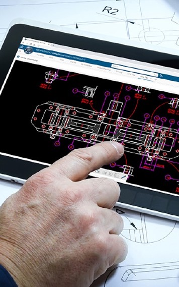
With computer aided design software, designers and engineers can simulate objects digitally, refining designs before production. This software enables precise technical drawings, eliminating manual drafting, improving efficiency, accuracy, and facilitating team collaboration.
Understanding Computer Aided Design: The Basics
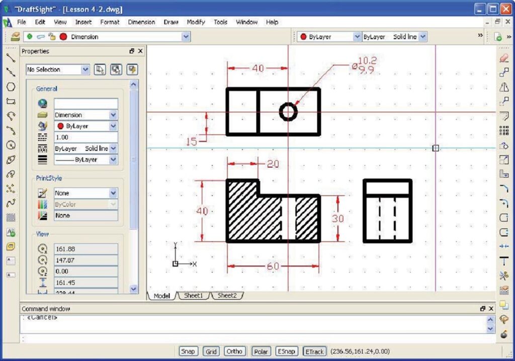
Gone are the days of using pencils, rulers, and protractors to create blueprints. Computer aided design allows engineers to create 2D and 3D models of objects, complete with scale, precision, and physics properties.
Use a combination of digital creation tools, such as lines, circles, and curves, to craft desired shapes and geometries, and even add annotations, dimensions, and other details to your models. These can then be manipulated, tested, analyzed, and easily modified for faster iteration and higher overall quality.
A Quick Blueprint for the Core Components of a CAD System
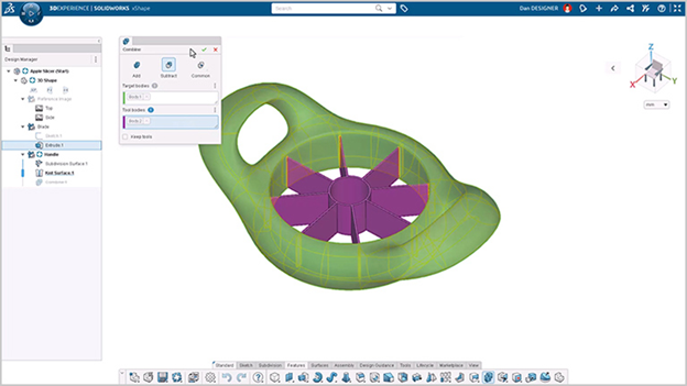
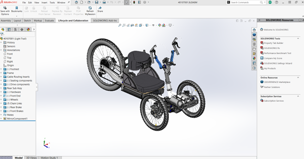
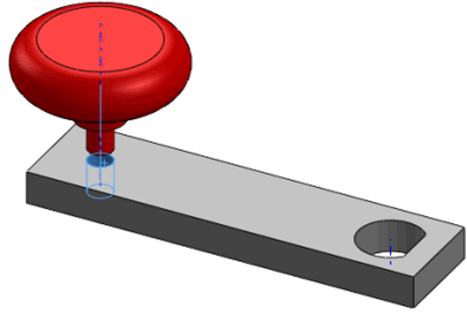
- Solid modeling: A fundamental feature that allows designers to create realistic 3D representations of objects. Solid models are built by joining 3D surfaces and can accurately depict the dimensions and attributes of the object.
- Parametric modeling: Establish relationships between different parts of a detailed design. For example, when one part of a model is modified, other related components adjust accordingly, ensuring consistency.
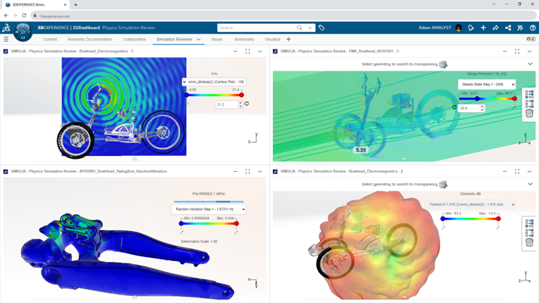
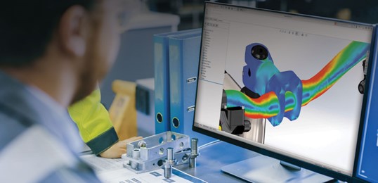
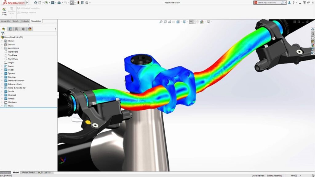
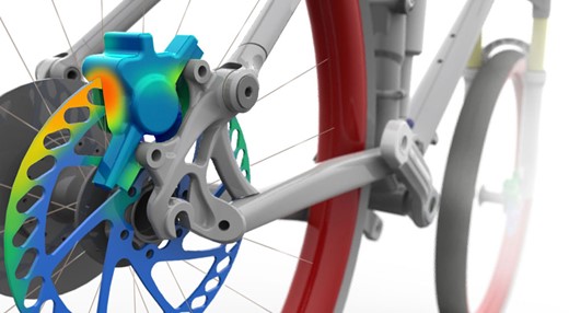
- Simulation: Simulate how a design will perform under various conditions, such as stress, heat, or fluid flow. Identify potential issues early in the design stage and make necessary adjustments to improve final performance and reliability.
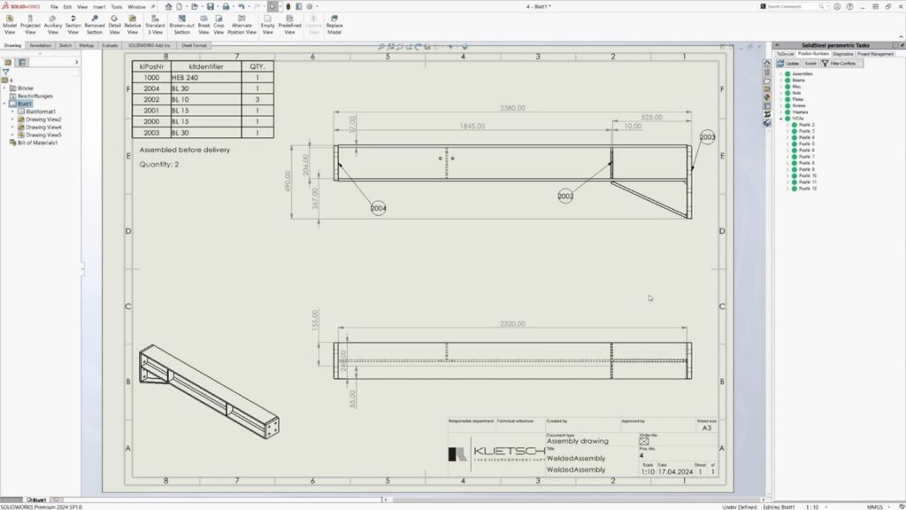
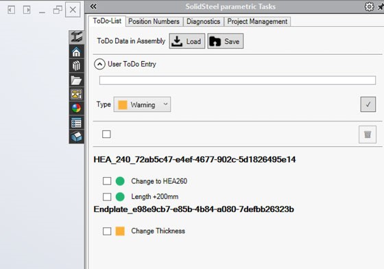
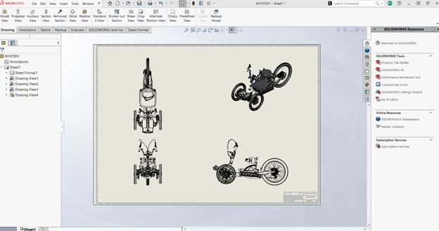
- Documentation: Easily create detailed technical documentation for your 3D models, including technical drawings, bills of materials (BOMs), and assembly instructions.
Together, these core components enable you to create detailed and precise designs while simplifying the process, making it easier to iterate on and improve overall quality.
Distinguishing Between 2D, 2.5D, and 3D CAD
- 2D: Primarily used for creating 2D drawings. It allows designers to create flat representations of objects using fundamental geometric shapes such as lines, rectangles, and circles. Most commonly used for architectural floor plans, electrical circuit diagrams, and technical illustrations.
- 2.5D: Also known as prismatic modeling. Allows designers to create models with depth. While the objects created in 2.5D are three-dimensional, they do not have overhanging parts. Often used for creating molds, toolpaths for machining, and other applications where a limited level of depth is required.
- 3D: Enables designers to create realistic 3D models of objects. Accurately represents the dimensions, shape, and attributes of the object. Widely used in industries such as automotive, product and industrial design, and engineering projects.
How does Computer Aided Design Software Work?
The simple answer? A computer does all the heavy lifting for you! No more crooked drawn lines, scribbled dimensions, or confusing design intent. Just clear, shareable 3D representations of your coolest inventions.
Your CAD software features simplify the process with a user-friendly interface and powerful tools for creating 3D designs. It allows you to visualize your ideas in a digital environment, and makes it easier to iterate and improve the design before manufacturing.
Integration with Other Tools and Platforms: CAM, Documentation, Simulation, and More!
Integration with other tools and platforms allows designers to leverage the strengths of each tool and create a seamless design process.
- Computer Aided Manufacturing (CAM): Automate the manufacturing process. CAM software uses 3D models to generate toolpaths for machining operations, allowing for efficient and accurate production.
- Simulation Software: Analyze the behavior and performance of your design. Simulate various factors such as stress, heat transfer, and fluid dynamics.
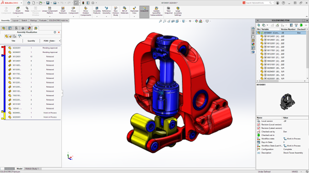
- Product Lifecycle Management (PLM): a centralized repository for managing data and collaboration among design teams. Easily exchange data, manage version control, and workflow management.
Revolutionizing Industries Worldwide
Computer aided design has revolutionized various industries, enabling designers and engineers to create precise and optimized designs, enhancing efficiency, accuracy, and innovation in the invention processes.
Automotive Design and Manufacturing
In the past, the automotive industry relied heavily on manual drafting and physical prototypes. CAD models have replaced these traditional methods, allowing designers to create accurate digital models and simulate real-world behavior. With the help of systems like SOLIDWORKS and CATIA, automotive designers can now use CAD for conceptual mechanical design, creating realistic 3D models of vehicles, optimizing performance, and streamlining manufacturing.
Also, digital collaboration among teams, suppliers, and manufacturers improves communication and reduces errors. Like sending a text message, instead of a carrier pigeon!
Architecture and Construction
Powerful computer-calculated simulations, depicting how a building will look and function, empower architects to make informed decisions about elements such as lighting, acoustics, and energy efficiency. With less time and effort spent on drawing physical blueprints and decoding the notation styles and penmanship of their peers, architects are freed up to experiment with different materials and never-before-seen designs.
In the construction industry, specialized tools help create drawings and models with a significantly higher level of detail, facilitating communication and coordination between architects, engineers, and contractors. This ensures designs meet building codes and regulations for systems like HVAC, electrical, and plumbing.
SOLIDWORKS: A Leader in 3D Design Technology
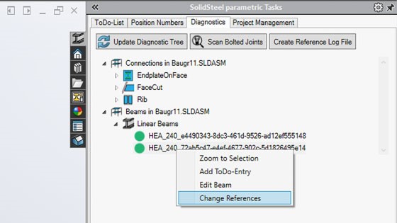
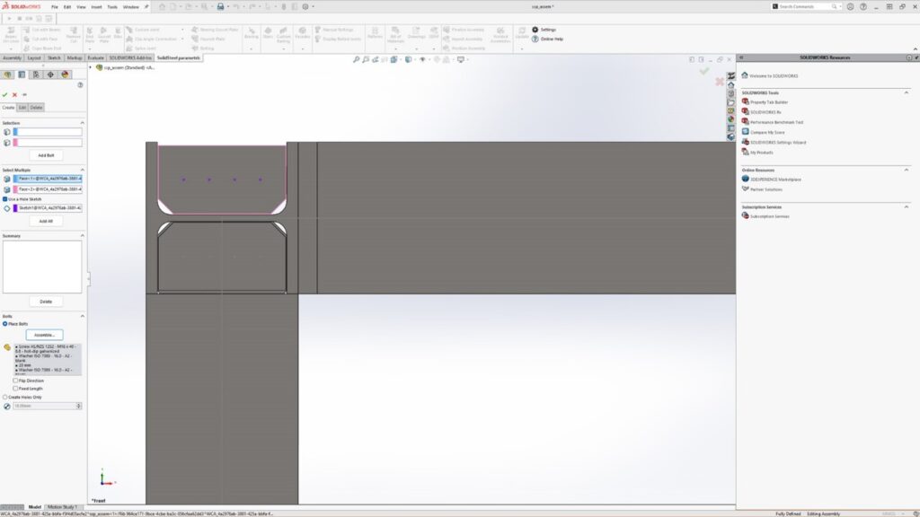
Industry-leading SOLIDWORKS is globally known for its reliable solid modeling capabilities and user-friendly interface. It offers a comprehensive set of tools for creating, modifying, and analyzing 3D models so designers can create realistic 3D models incorporating detailed dimensions, standard materials, and physical properties.
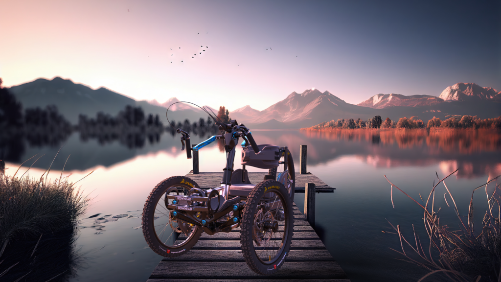
With SOLIDWORKS, you can simulate real-world behavior, perform stress analysis, and create photorealistic renderings of your designs. The software also provides advanced features for sheet metal design, welding, assembly modeling, and more!
Practical Applications
Computer aided design helps streamline production processes, enables prototyping with 3D printing, and enhances collaboration among design teams.
- Streamlining Production: Create accurate and detailed manufacturing drawings, optimizing production processes and reducing errors. Enable efficient material usage, precise machining instructions, and documentation of the production process.
- Prototyping with 3D Printing: Create physical prototypes of your 3D models using 3D printing technology. Quickly iterate and test designs, saving the time, costs, and headaches associated with traditional prototyping methods.
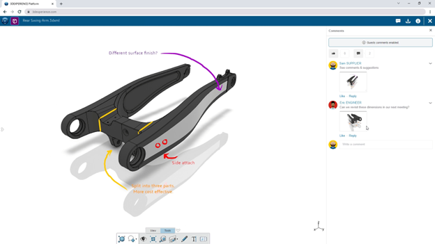
- Enhancing Collaboration: Encourage multiple designers to work on the same project simultaneously with real time communication, version control, and documentation sharing for improved efficiency and fewer errors.
Streamlining Production Processes
CAD software boosts production efficiency by streamlining processes, cutting time and costs. Create detailed manufacturing drawings to ensure products meet specifications. Identify and fix manufacturing issues early, reducing errors.
CAD can also optimize your material usage, reduce waste, and maximize your cost savings. It assists in designing objects like jewelry, furniture, and appliances, documenting revisions and quality control procedures for consistency and traceability, enhancing your process efficiency and product quality.
Fast and Easy Prototyping with 3D Printing
CAD software revolutionizes prototyping by allowing you to create physical prototypes from digital models using 3D printing. It enables quick iteration, testing, and cost reduction. Simulate product behavior, modify designs, and produce complex shapes in various materials such as plastics, metals, and composites to ensure optimal performance.
Enhanced Real Time Collaboration
Computer aided design software improves collaboration among design teams by enabling real time communication. It allows multiple designers to work together simultaneously, share work, make modifications, and provide feedback instantly. Easily share designs with clients and manufacturing teams, improving communication and reducing errors. With features like version control and revision tracking, you can ensure consistency, meet project deadlines, and centralize design communication, documentation, and feedback for enhanced efficiency and seamless teamwork!
Advancements and Future Trends
Computer aided design technology continues to evolve, with advancements and future trends shaping the way designers and engineers work. These advancements seek to simplify the design process, so passionate inventors can focus on what they do best: Innovate!
The Rise of the Cloud-Based Platform
Cloud-based CAD platforms, like the 3DEXPERIENCE platform, offer increased accessibility and collaboration compared to traditional on-premises software. Access files from anywhere, eliminate the need for physical storage, and enable seamless collaboration.
Multiple designers can work together in real time, streamlining the design process and improving efficiency. These platforms also provide scalability, allowing designers to adjust usage as needed by adding or removing users and accessing additional features. The rise of real time cloud-based CAD has revolutionized the design industry with enhanced accessibility, collaboration, and flexibility.
Learn more about moving to 3D with the 3DEXPERIENCE in our blog post, here.
AI and Machine Learning in CAD
AI and machine learning have revolutionized CAD by automating conceptual design processes, optimizing designs, and improving simulation capabilities. Generative design generates options based on constraints, allowing for exploration of various possibilities. Machine learning algorithms learn from feedback to offer intelligent design recommendations. They enhance simulation accuracy, leading to more reliable designs.
As AI progresses, CAD software will become more efficient and capable of automating complex tasks, promising innovation in design creation.
Overcoming Challenges in CAD
By addressing challenges through training and support, designers and engineers can maximize the benefits of their software and overcome any hurdles between them and brining their ideas to life.
Addressing the Learning Curve
Using CAD software can be challenging due to its complexity, requiring users to learn new tools and workflows. To help with this learning curve, your friendly neighborhood experts (that’s us!) offer training resources, and community support. Our training resources offer structured learning experiences for CAD users of all proficiency levels.
Community support enables users to connect with others, ask questions, and share experiences to enhance proficiency in CAD software. Leveraging these resources can help you unlock the full potential of CAD software.
Navigating Software Compatibility Issues
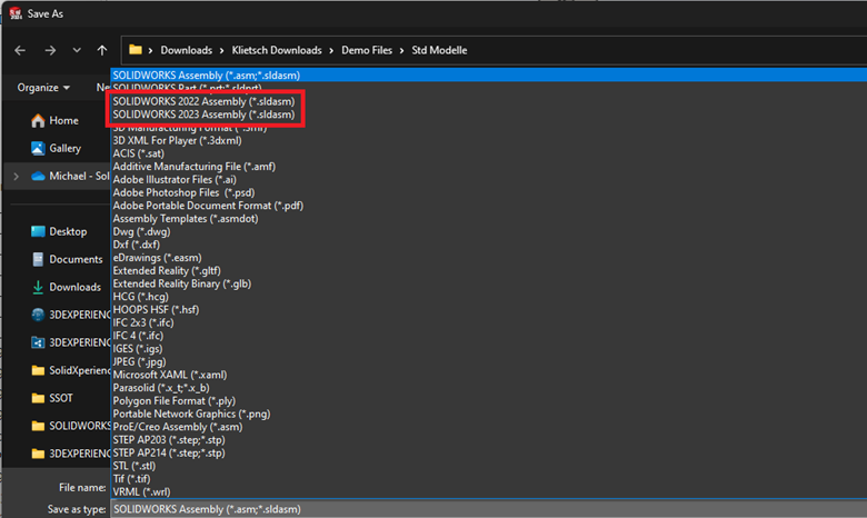
CAD software compatibility is crucial. Different programs have unique file formats, posing challenges for data exchange and collaboration. Opt for software supporting neutral formats like STEP, IGES, or JT for better interoperability. Alternatively, choose software with native formats for enhanced data accuracy, though limited accessibility. Consider industry-wide acceptance for smooth collaboration.
Conclusion
CAD software is pivotal across industries, from automotive to architecture, by optimizing production workflows, fostering collaboration, and spearheading technological advancements. As cloud-based platforms evolve and AI and machine learning become more integrated, the potential for CAD in the future is boundless.
Want to learn more? Take a look at our recent blog post about transitioning to 3D technology, here.
Frequently Asked Questions
Is it hard to learn SOLIDWORKS?
Learning SOLIDWORKS can be challenging for beginners due to its robust features and functionalities. However, with dedication, practice, and leveraging available tutorials and training resources, users can overcome the learning curve and become proficient in using SOLIDWORKS for various design and engineering tasks. Remember, practice makes perfect!
Can CAD Software Be Used for Animation?
Yes, CAD software can be used for animation. While CAD software is primarily used for designing and simulating real-world objects, it also has features that allow for visualization and animation. This can be useful for creating realistic representations of design projects and showcasing how a they would function in real life.
How Has CAD Influenced Product Development?
CAD has had a significant impact on product design. It has revolutionized the entire process by allowing engineers and designers to create and modify designs in a digital environment. CAD has enabled innovation, improved efficiency, and customization in product design, leading to the development of better and more complex products.

Any questions? Need help? Ask one of our experts.
Whether you’re ready to get started or just have a few more questions, you can contact us toll-free: