SOLIDWORKS CAD 2024 is a landmark release that redefines the 3D CAD landscape. Driven by user feedback, it introduces groundbreaking features that promise to revolutionize design, engineering, and collaboration. This year’s release is guided by 3 major principles that seek to define the future of Computer-Aided Design:
- Efficiency is a constant focus. Streamlined workflows in assemblies, parts, features, and drawings simplify complex tasks. Features like the Defeature Silhouette option make large assembly management a breeze while previewing and editing dimensions upon entity selection saves valuable time.
- Clear communication is critical. Enhanced chain dimensioning and the ability to exclude hidden sketches ensure that design intent is communicated accurately.
- Intelligent and flexible workflows are paramount. Whether you’re working on sheet metal designs, complex structures, electrical routing, or comprehensive documentation, SOLIDWORKS equips you with tools to work more intelligently.
With the release of SOLIDWORKS CAD 2024, users can expect a host of innovative enhancements designed to improve productivity, communication, and collaboration. In this article, we’ll dive into the top ten enhancements that SOLIDWORKS has in store for its users in the 2024 release.
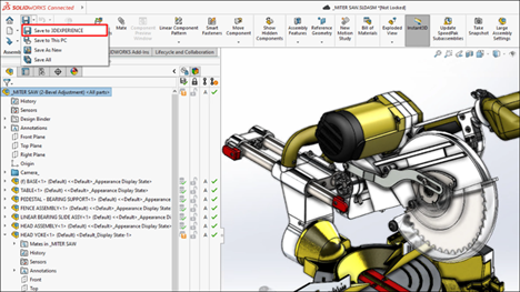
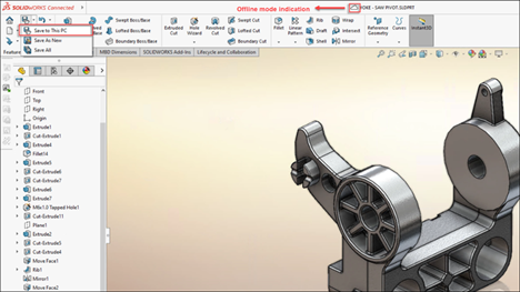
- #1 Previous Release Compatibility: Collaborate Seamlessly
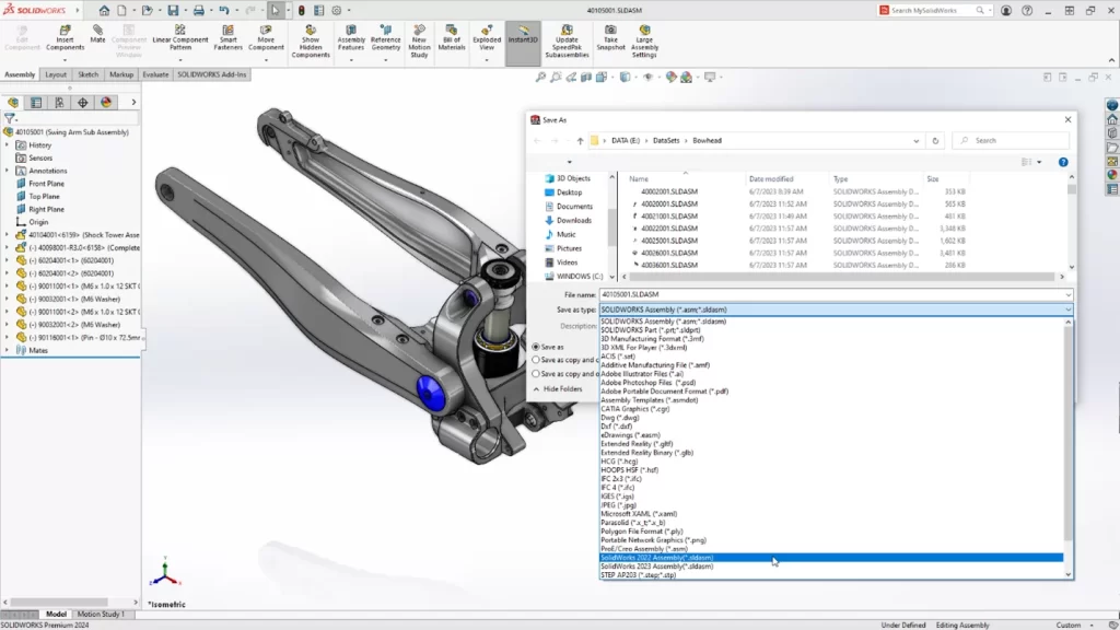
SOLIDWORKS CAD 2024 introduces a game-changing feature – Previous Release Compatibility. This allows users to save their files in formats that are compatible with SOLIDWORKS versions up to two years prior to the latest release. This means you can collaborate effortlessly with colleagues or clients who might be using older versions of the software, eliminating compatibility issues, and streamlining your workflow.
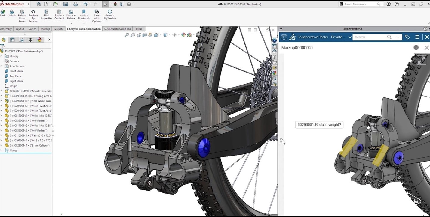
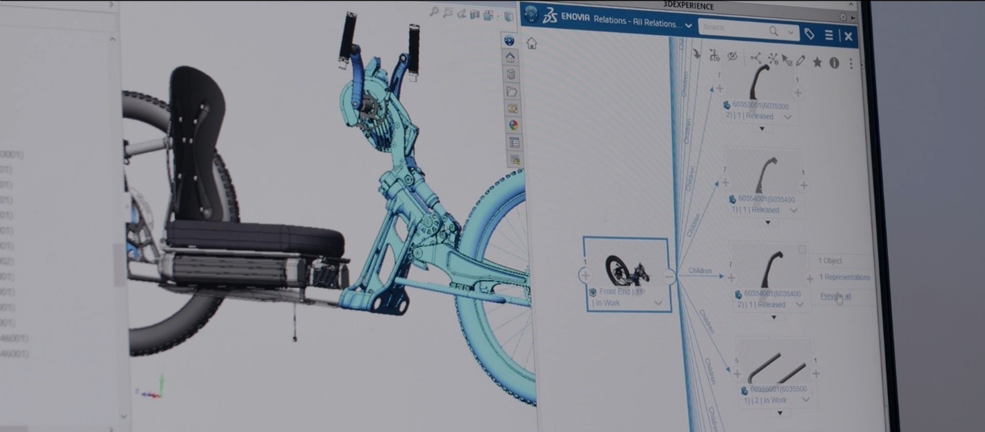
- #2 Assemblies: Streamlined Design and Collaboration
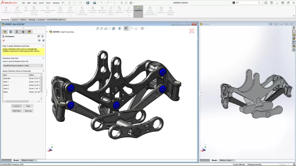
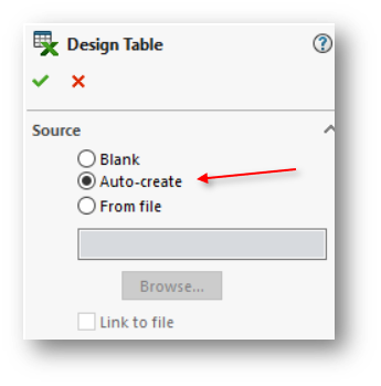
In large assembly projects, efficiency is crucial. SOLIDWORKS CAD 2024 simplifies large assembly design, documentation, and collaboration with several new features. The Defeature Silhouette option allows you to create simplified versions of your models based on criteria such as custom property, mass property, and file name. You can also represent post-assembly machining operations using the “Insert Assembly into Part” feature.
- #3 Parts and Features: Sketching and Dimensioning Made Easy
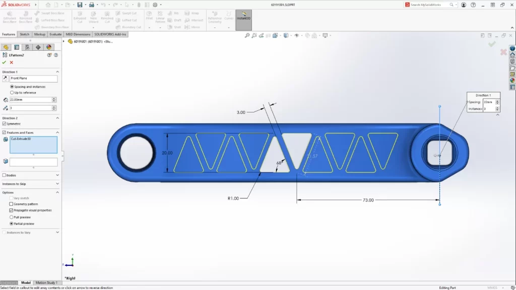
This release focuses on making sketching and dimensioning more efficient. You can now preview and edit dimensions as soon as you select one or more entities. The new Symmetric option for Linear Patterns simplifies bidirectional, symmetric patterns. Additionally, displaying the unit of measurement as a custom property in notes and tables ensures clarity in your design intent.
- #4 Drawings and Detailing: Clear Communication
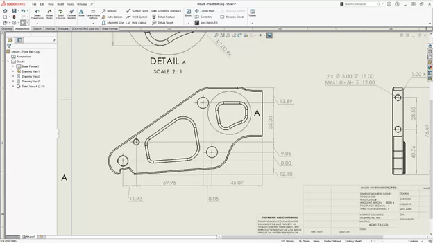
Clear and efficient communication is vital in engineering. SOLIDWORKS CAD 2024 enhances your drawing and detailing capabilities. Improved chain dimensioning alignment and adherence to drawing standards ensure that your design intent is communicated clearly. Dangling dimensions can be cleaned up more efficiently by reattaching them to the proper reference points. You can also exclude hidden sketches from DXF™ Flat-Pattern, reducing post-processing work.
- #5 Sheet Metal: Meeting Manufacturing Standards
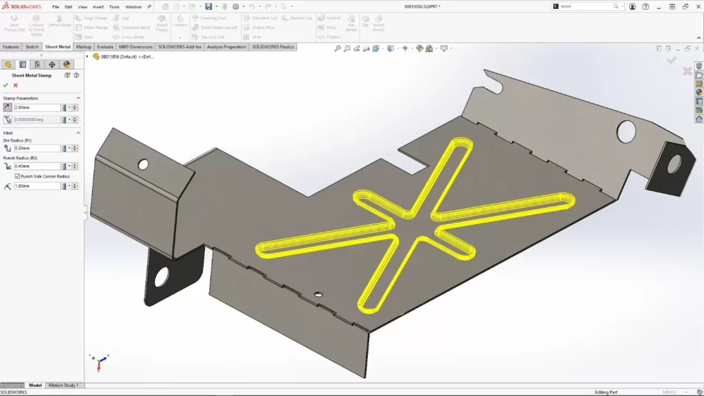
Sheet metal design is made easier in the 2024 release. The new Rip tool lets you create rips in hollow or thin-walled cylindrical and conical bodies, simplifying the flattening process. Other enhancements include the Normal Cut option for slots when tabs are created at an angle and the automatic propagation of slots to all instances of a tab that intersects a specific part. You can even create a stamp/form feature on the fly using just a Sketch, eliminating the need for form tool creation.
- #6 Structure Systems: Faster and Easier Weldments
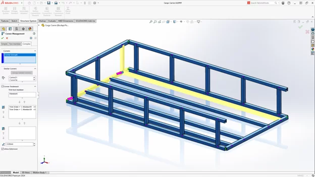
Creating weldments becomes faster and requires fewer modifications in SOLIDWORKS 2024. With improved corner treatment functionality, you can speed up the editing and management of corner treatments. The software now automatically creates an open corner for the addition of a connection block with a new corner treatment option, saving valuable time in your design process.
- #7 Routing: Complex Electrical Routing Made Easy
Handling complex electrical routing scenarios is more straightforward with new options for flattening, reorienting, and displaying wires and connectors. You can update only the current 3D electrical route and add electrical routes as either single segments or as groups of discrete wires in electrical bundles. These enhancements enhance routing design clarity and efficiency.
- #8 SOLIDWORKS Electrical: Speedier Documentation
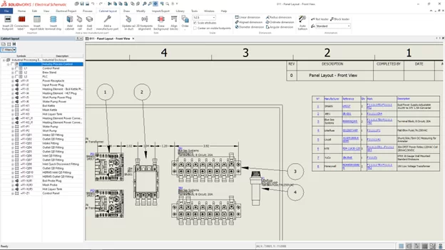
Better performance is a constant priority, and SOLIDWORKS Electrical delivers just that. Key enhancements include the ability to insert auto balloons in SOLIDWORKS Electrical 2D cabinet layout drawings and the ability to shorten lists using ranges. Excel automation now automatically resets undefined macro variables, making documentation more informative and faster.
- #9 SOLIDWORKS MBD: Clear Communication Downstream
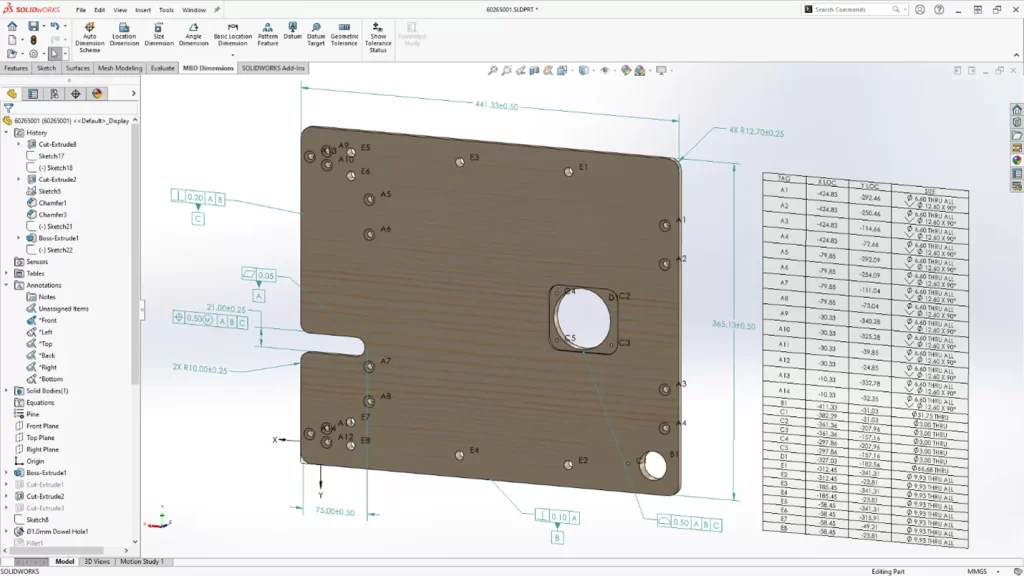
In SOLIDWORKS MBD, several updates improve communication downstream to manufacturing. These include the ability to export a hole table when publishing a part to 3D PDF, edit dangling dimensions and reattach them to a feature in the model, and export custom properties from a part or assembly to the STEP 242 format. These updates ensure your design intent is communicated clearly in 3D.
- #10 SOLIDWORKS Visualize: Realistic Renderings
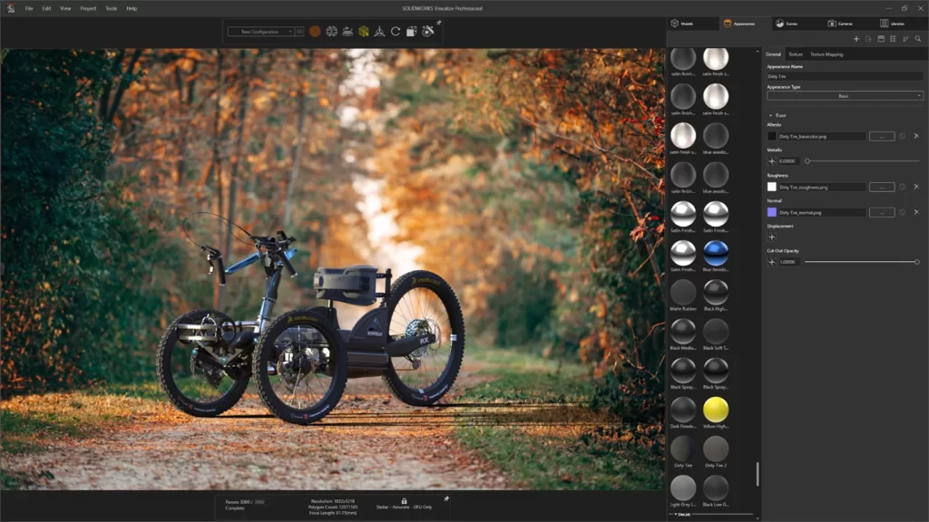
SOLIDWORKS Visualize allows users to create compelling appearances with advanced real-life rendering capabilities. You can now select appearance types and optimize their parameters more easily with a simplified interface. Adjusting textures and texture maps provides greater control and fidelity. Combining normal and displacement maps and applying vector displacement allows you to replicate the realistic appearance of various surfaces, from metal to glass to plastic.
SOLIDWORKS CAD 2024 is a powerful and user-centric release that underscores its position as a leader in 3D CAD software. With an unwavering commitment to user-driven innovation, a focus on interoperability and collaboration, streamlined workflows, improved clarity and communication, and increased efficiency and productivity, SOLIDWORKS empowers engineers and designers to tackle their most challenging projects with confidence. As technology continues to evolve, SOLIDWORKS remains a reliable partner for professionals seeking to bring their design visions to life with greater ease and effectiveness.

Any questions? Need help? Ask one of our experts.
Whether you’re ready to get started or just have a few more questions, you can contact us toll-free: