When we talk about digital transformation in manufacturing, we often picture smart factories, IoT, robotics, or even artificial intelligence. Yet, there’s a critical, and sometimes underestimated, stage that initiates this transformation: the digital design of products using CAD software for manufacturing. This is precisely where SOLIDWORKS comes in.
Developed by Dassault Systèmes, SOLIDWORKS has long been a key player in the world of Computer-Aided Design (CAD). But today, its role extends well beyond drafting and modeling. As powerful CAD software for manufacturing, SOLIDWORKS sits at the core of the digital manufacturing chain, acting as a bridge between creativity and production, and integrating with data management, simulation, process automation, and enterprise systems.
At Solidxpets, we help businesses implement these technologies across their operations. With the hands-on support of our experts, you can count on real-world guidance for deploying the full SOLIDWORKS portfolio.
From 3D Modeling to the Shop Floor: A Seamless Transition with CAD Software for Manufacturing
While 3D modeling is already a step toward digitization, it becomes far more powerful when integrated with the rest of the production workflow. That’s why a fully connected digital chain, from design to delivery, is so vital.
With the 3DEXPERIENCE® Works platform, SOLIDWORKS becomes more than a design tool. It is a collaborative hub that connects departments, suppliers, customers, and even machines. As CAD software for manufacturing, it ensures your designs flow seamlessly into production.
This connectivity leads to:
-
Shorter lead times
-
Improved decision traceability
-
Clearer interdepartmental communication
-
Enhanced agility
Smart 3D Modeling and Integrated Simulation in CAD Software for Manufacturing
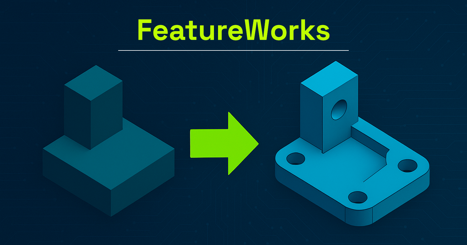
SOLIDWORKS provides robust parametric 3D modeling tools, enabling precise control over parts, assemblies, and configurations. These models can be easily reused, modified, and scaled.
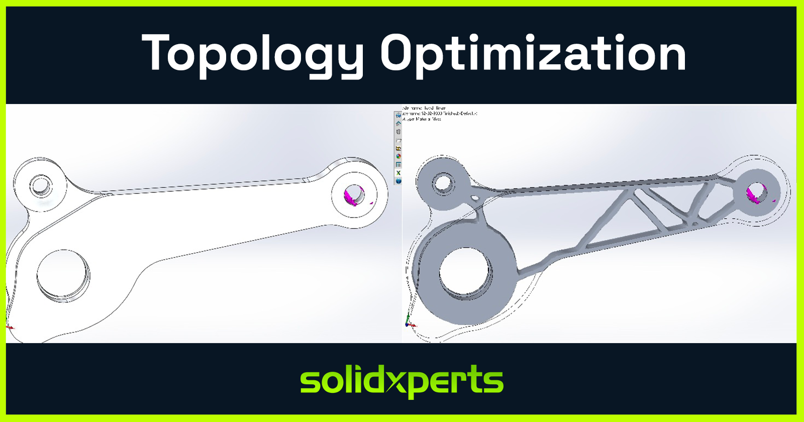
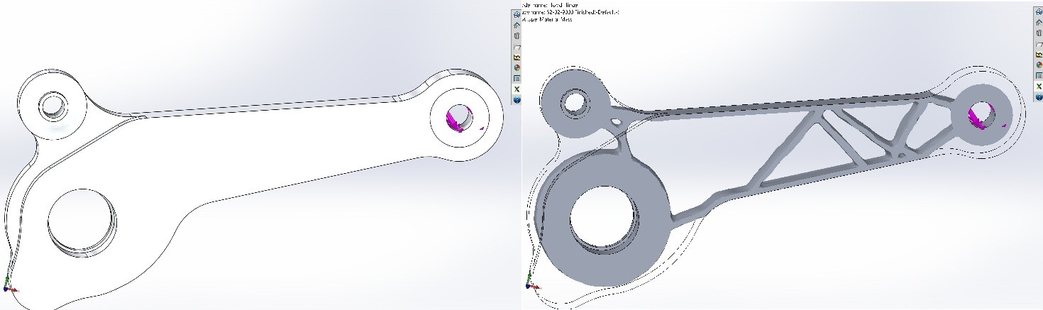
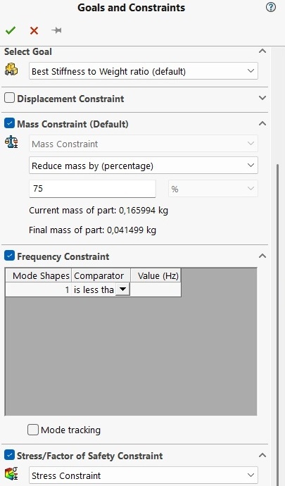
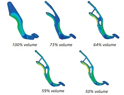
The real game-changer is simulation. With SOLIDWORKS Simulation, a core component of CAD software for manufacturing, engineers can:
-
Test structural integrity under load
-
Predict deformation and failure
-
Analyze fluid dynamics and airflow
-
Evaluate thermal performance
All of this happens before manufacturing begins, drastically reducing prototypes, costly rework, and delays.
Connected, Flexible Manufacturing Tools Powered by CAD Software for Manufacturing
The 3DEXPERIENCE® Works portfolio includes purpose-built tools for the factory floor:
-
Shop Floor Programmer: Allows CNC programmers to create and simulate 2.5- and 3-axis toolpaths, generate wire EDM operations, and detect potential collisions during production.
-
Robot Programmer: Enables fast and easy programming, simulation, and deployment of robotic routines without disrupting current production lines.
-
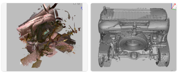
Factory Simulation Engineer: Simulates plant layouts and production flow using 2D, 3D, or point cloud environments, helping optimize floor space and logistics.
Together, these tools form a closed-loop ecosystem between design and manufacturing, ensuring continuous feedback and real-time synchronization.
Collaboration and File Management: A Strategic Necessity in CAD Software for Manufacturing
In manufacturing, engineering data is a strategic asset. Managing this data becomes increasingly complex with more iterations, collaborators, and file versions.
With SOLIDWORKS PDM and the 3DEXPERIENCE platform, both integral to modern CAD software for manufacturing, companies can:
-
Centralize all product data
-
Control revisions and user access
-
Collaborate securely via the cloud
-
Track every design change, comment, and approval
This level of traceability is essential, especially in highly regulated industries like aerospace, medical devices, or defense.
ERP Integration with CAD Software for Manufacturing: Real-Time Data Flow Across the Business
Enterprise Resource Planning (ERP) systems are at the heart of business decision-making. Yet in many organizations, CAD remains disconnected from the main information system.
Integrating SOLIDWORKS CAD software for manufacturing with ERP software like SAP, Oracle, or Microsoft Dynamics allows for:
-
Automatic transfer of Bill of Materials (BOMs)
-
Real-time work order generation
-
Cost estimation based on materials and machine time
-
Elimination of redundant data entry
This creates a direct link between design and operations, boosting organizational responsiveness and reducing costly delays.
At Solidxperts, we offer proven connectors and services for integrating SOLIDWORKS with leading ERP systems so your business runs smoother from day one.
Cloud Solutions for Distributed Teams Using CAD Software for Manufacturing
As remote and hybrid work models become standard, secure and flexible cloud access to CAD data is more critical than ever.
The 3DEXPERIENCE platform provides centralized, cloud-based project spaces with:
-
Anytime, anywhere access to design files
-
Real-time collaboration
-
Browser-based viewing and markup
-
Built-in security and automatic backups
For teams using CAD software for manufacturing, this means faster decision-making, improved communication, and a single source of truth for every stakeholder.
Automating Business Processes with CAD Software for Manufacturing
Beyond CAD, the 3DEXPERIENCE platform empowers users to digitize business workflows such as design validation, quality approvals, and production launches.
With low-code and no-code tools, you can:
-
Build simple, intuitive apps for non-technical staff
-
Automate approval workflows
-
Eliminate repetitive manual tasks
By embedding automation into CAD software for manufacturing, companies can save time, reduce errors, and accelerate product launches.
People Matter: Training and Expert Support for CAD Software for Manufacturing
A digital manufacturing chain is only as strong as the people behind it. Even the most powerful tools are ineffective without proper training and adoption.
That’s why Solidxperts offers:
-
Certified training on SOLIDWORKS and 3DEXPERIENCE
-
In-depth audits to identify process improvement opportunities
-
Bilingual technical support based in North America
-
Pilot projects to support change management
The best CAD software for manufacturing is only as good as its users, and the right training ensures you get maximum value from your investment.
Conclusion: The Role of SOLIDWORKS CAD Software for Manufacturing in the Digital Manufacturing Chain
SOLIDWORKS is far more than a design tool. It is a foundational element in the digital manufacturing chain, enabling companies to innovate, streamline production, and stay competitive in an evolving market. By connecting SOLIDWORKS CAD software for manufacturing with the 3DEXPERIENCE® Works platform, businesses gain access to simulation, cloud collaboration, manufacturing tools, and process automation, all within one agile, integrated ecosystem. This strategic integration empowers organizations to work smarter, adapt faster, and achieve long-term success in the era of Industry 4.0.
At Solidxperts, we believe this transition must be strategic, personalized, and scalable. In other words, tailored to your company’s unique reality. Ready to take the next step? Contact our experts.


Any questions? Need help? Ask one of our experts.
Whether you’re ready to get started or just have a few more questions, you can contact us toll-free: