Key Highlights
- Design for Additive Manufacturing (DfAM) allows you to create lighter, higher-performing, and potentially cheaper-to-produce 3D prints.
- DfAM enables mass customization, performance optimization, reduction of material waste, and supply chain simplification.
- Additive manufacturing accelerates time-to-market by speeding up prototyping and testing phases.
Introduction
Understanding Design for Additive Manufacturing (DfAM) is crucial for those of us using 3D printing. Additive Manufacturing (AM), an industry term for 3D printing, offers benefits like lighter, higher-performing parts, and customization. To help you maximize your AM advantages, this guide covers DfAM basics, explores AM capabilities, and details design optimization techniques. Discover how DfAM impacts product development, cost efficiency, and time-to-market acceleration to transform your production processes.
Exploring the Fundamentals of Design for Additive Manufacturing (DfAM)
Design for Additive Manufacturing is the practice of designing and optimizing your 3D models and designs, with the ultimate goal of 3D printing the final piece. Mastering Design for Additive Manufacturing requires understanding basic concepts and adapting to advancing technologies and best practices.
Understanding the Unique Capabilities of Additive Manufacturing
AM offers unique capabilities that differ from traditional methods. You can optimize concepts for superior performance by leveraging these capabilities.
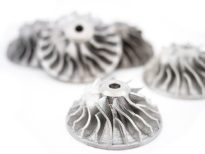
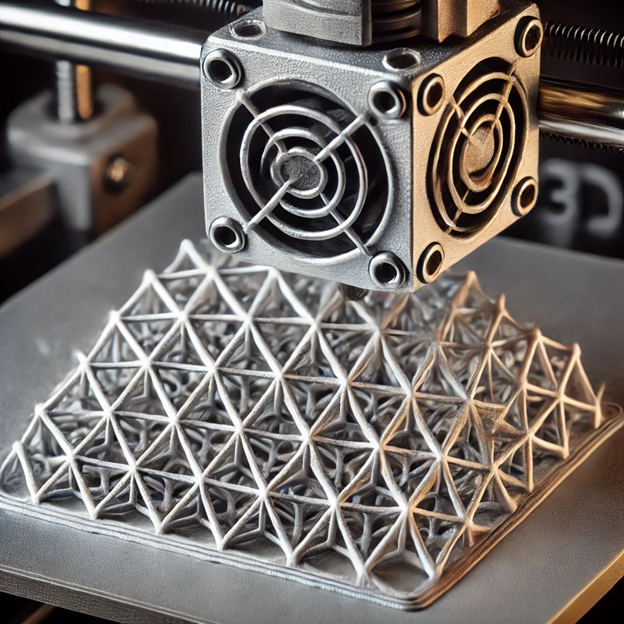
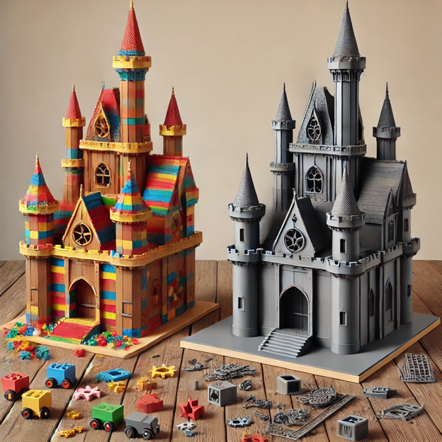
One key feature is the ability to create intricate geometries that are challenging or even impossible through traditional methods, allowing for lightweight, high-performance designs. It also enables customized products tailored to user needs and design optimization through variable densities and internal structures.
By utilizing these capabilities, you can innovate and push beyond traditional manufacturing limitations.
Key Principles of DfAM for Optimizing Design
Design for Additive Manufacturing involves several key principles that are essential for optimizing concepts. By following these principles, you can take full advantage of the benefits offered by AM.
- Part consolidation: By combining multiple components into a single part, you can reduce weight, assembly time and costs, and potential points of failure.
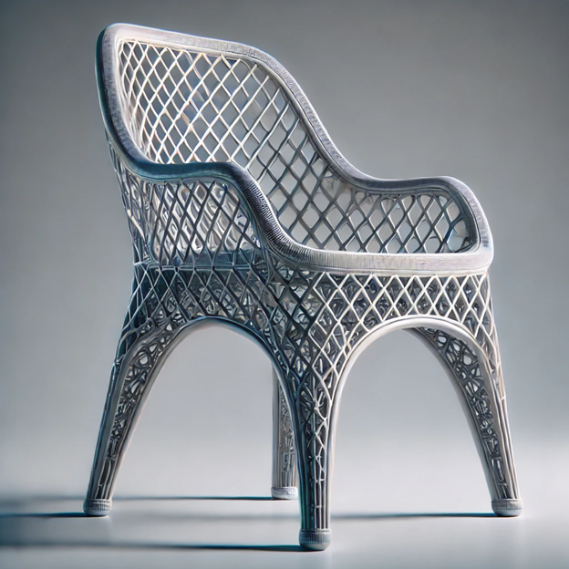
- Architected materials: Manipulating the properties of lattice structures and surface textures allows for the creation of highly customizable and tailored materials with specific mechanical, biological, thermal, or electromagnetic properties.
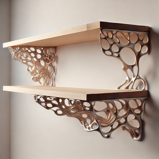
- Generative design: Using computational algorithms, generative design generates high-performance geometry based on specific requirements, resulting in lighter, stronger, and more efficient designs in less time.
- Topology optimization: This process seeks to produce an efficient material distribution to solve a particular problem, resulting in lightweight yet structurally sound parts.
By incorporating these principles in the design process, you can create optimized and innovative designs that fully exploit the capabilities of 3D printing.
Innovative Design Strategies for 3D Printing
AM enables innovative design strategies not possible with traditional methods. One key strategy is using complex geometries to optimize performance. Another is selecting materials carefully for enhanced product performance, durability, and functionality. By leveraging these strategies, designers can create groundbreaking designs that fully exploit AM’s potential.
Embracing Complexity: How to Leverage Complex Geometries
AM allows for complex geometries, empowering you to create innovative and high-performance products that were unachievable with traditional methods. Intricate shapes optimize functionality and performance, pushing design boundaries for visually appealing products that enhance structural integrity and reduce weight. Designers can leverage this design freedom to create lightweight, robust structures optimized for specific applications. Considerations such as part orientation, support structures, and material selection are crucial for fully utilizing complex geometries in AM.
Material Considerations for Enhanced Performance
Material selection is vital in AM, impacting the final product’s performance and functionality. Designers can optimize designs by considering material properties. AM offers various materials like polymers, metals, ceramics, and composites, each with unique properties. Choosing the right material ensures desired performance. AM allows for creating hybrid materials and combinations to tailor product properties. By exploring new material possibilities, you can maximize your AM capabilities for high-performance, high-quality products.
Cost Efficiency Through Additive Manufacturing
Optimizing designs for AM minimizes material waste and maximizes cost efficiency. This method allows for complex geometries and customized designs in a single step, reducing assembly needs and labor costs. By integrating cost efficiency in the design process, you can achieve substantial savings with AM.
Reducing Material Waste with Strategic Design
AM minimizes material waste through optimized design, reducing costs efficiently. Unlike traditional methods, it builds parts layer by layer, allowing precise material usage. Strategic design includes part consolidation, lightweighting, and functional feature integration to eliminate waste and maximize efficiency in AM.
Accelerating Time-to-Market with DfAM
Accelerate new product launches by leveraging AM’s benefits. Rapid prototyping and testing enable quick validation, faster iterations, and optimized designs. On-demand production reduces lead times and inventory needs, meeting market demands promptly. DfAM principles give designers a competitive edge, ensuring products meet requirements efficiently.
Speeding Up Prototyping and Testing Phases
Improve prototyping and testing cycles in product development. AM allows for rapid production of functional prototypes, reducing lead times and costs compared to traditional methods. You can iterate quickly without costly tooling, improving product quality early on. DfAM speeds up development, leading to faster time-to-market.
Advanced Techniques in DfAM
Beyond basic DfAM, these methods include complex design strategies and optimization. Design automation, using computational algorithms, streamlines repetitive tasks, saving time. Hybrid advanced manufacturing merges additive methods with traditional techniques like casting or injection molding, offering productivity gains and broader design options.
By integrating these techniques, designers can innovate and create optimized products.
Exploring Generative Design and Topology Optimization
Generative design and topology optimization are cutting-edge techniques in DfAM. Generative design uses algorithms to create innovative designs meeting specific requirements, while topology optimization optimizes material distribution for lightweight parts with superior mechanical properties. These techniques harness AM’s capabilities to produce intricate and efficient designs that are not easily achievable through traditional methods.
The Role of Part Consolidation in DfAM
Part consolidation combines multiple components into one, enabling more complex and optimized designs. This approach offers benefits like weight reduction, cost savings, increased reliability, and simplified supply chains. By identifying consolidation opportunities, engineers can enhance performance and functionality while reducing material wastage. DfAM allows designers to rethink products for AM technologies on a systems level.
Utilizing Simulation for Predictive Design Outcomes
Simulation is crucial in DfAM for predicting and optimizing design outcomes. It helps identify issues, enhance performance, and minimize failure risk by simulating design behavior under various conditions. Engineers can select the best manufacturing process and material for a design, ensuring successful production using AM technologies. Simulation enables informed decisions, design refinements, and desired functionality.
Conclusion
Mastering DfAM involves understanding the ever-evolving capabilities of 3D printing, optimizing designs for efficiency, and embracing innovative strategies like leveraging complex geometries and enhancing performance through material considerations. DfAM reduces material waste, accelerates time-to-market, and enhances product development through techniques like generative design and topology optimization. Embracing AM paves the way for a sustainable and agile manufacturing future by unlocking endless possibilities for creativity and efficiency in production.
Frequently Asked Questions
What is additive manufacturing and how does it differ from traditional manufacturing methods?
Additive manufacturing, or 3D printing, builds parts layer by layer from digital design data. Unlike traditional methods like injection molding or CNC machining, it doesn’t need molds or subtractive processes. This process allows for more design flexibility, complex geometries, and cost-effective production of customized parts.
What are the key benefits of designing for additive manufacturing?
Designing for additive manufacturing (DfAM) offers various benefits, including lighter, higher-performing designs, mass customization, reduced material wastage, simplified supply chains, and aesthetically pleasing organic appearances. DfAM also enables cost savings, improved functional performance, and the creation of complex geometries challenging to achieve with traditional methods.
How can the design process be optimized to take full advantage of additive manufacturing technologies?
To optimize the design process for additive manufacturing, designers should consider key factors such as part consolidation, architected materials, generative design, and topology optimization. They should also focus on designing for cost minimization, automating repetitive tasks, and leveraging the capabilities of additive manufacturing in combination with traditional methods.

Any questions? Need help? Ask one of our experts.
Whether you’re ready to get started or just have a few more questions, you can contact us toll-free:

 3D Creator Streamlines Your Design Workflow
 ABS (Acrylonitrile Butadiene Styrene)
 PETG (Polyethylene terephthalate glycol)
 Onyx by Markforged: High Performance Carbon Fiber