Benefits of Transitioning to 3D
Transitioning to 3D workflows with SOLIDWORKS Pro enhances product design accuracy, facilitates efficient collaboration through shared models, and provides realistic visualization from all angles. It streamlines your processes with advanced tools for not only CAD, but sheet metal modeling, CAM integration, reverse engineering and more, saving time and boosting productivity. Kick your boring 2D routines to the curb and unlock the full potential of your designs, elevating your product development process to the next level.

Key Highlights
- SOLIDWORKS Pro offers a seamless transition from 2D to 3D, enhancing the product development process.
- Transitioning to 3D offers benefits such as improved product design, efficient collaboration, and enhanced visualization.
- Key features like advanced modeling tools, sheet metal capabilities, and CAM integration.
- Integrating SOLIDWORKS Pro into your workflow offers additional benefits like powerful simulation, realistic visualization, and streamlined documentation.
Getting Started in 3D with SOLIDWORKS Pro
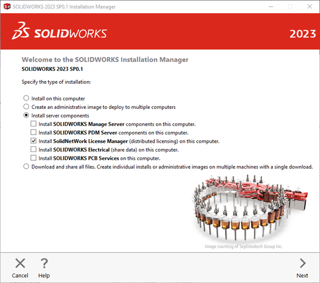
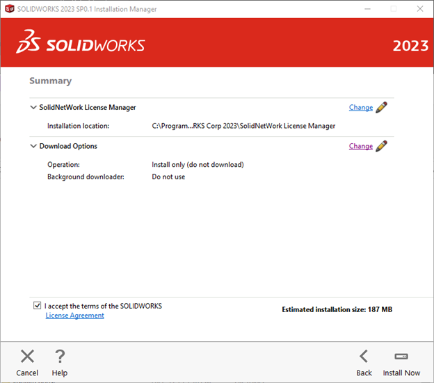
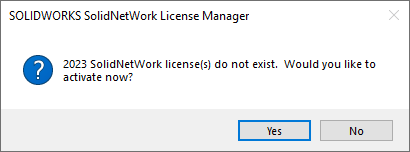
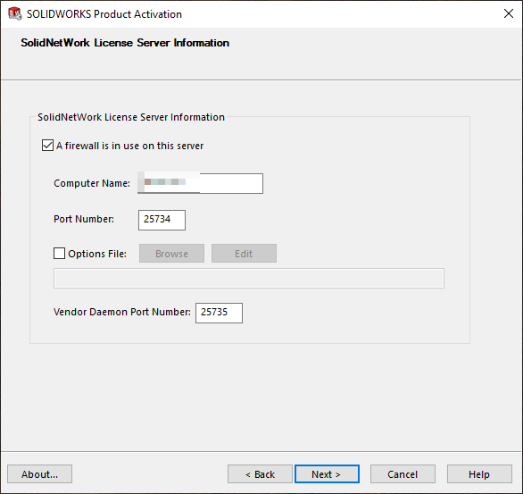
Congratulations on taking the first steps towards transitioning from 2D to 3D design! It all starts with a SOLIDWORKS Professional license and a dream. This shift opens up a world of possibilities, offering enhanced product design, efficient collaboration, and advanced visualization. As we delve into the possibilities, you will discover a full range of features designed to streamline your workflow, save time, and boost productivity.
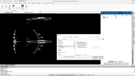
Integrating SOLIDWORKS Pro into your process will revolutionize the way you approach product development. By harnessing the power of shared 3D models and realistic visualization, this software empowers you to elevate your designs from every angle. With advanced tools for CAD, sheet metal modeling, CAM integration, and more, including the file management capabilities of SOLIDWORKS PDM Standard, you can bid farewell to mundane 2D routines and embrace a new era of efficiency and creativity.
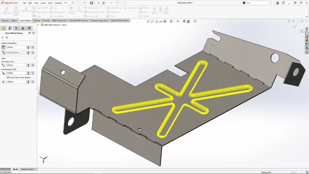
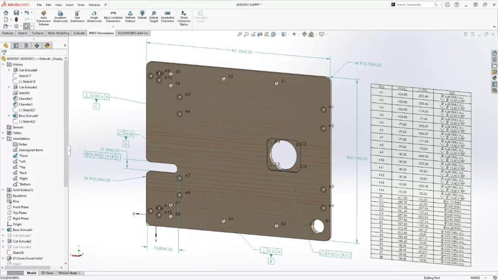
Key Features for 3D Modeling
SOLIDWORKS is robust 3D modeling software designed to help you create intricate designs. Its advanced tools enable smooth model creation and editing, including standard features such as sheet metal design, CAM integration, and stress analysis. The sheet metal features streamline the creation of sheet metal parts, encompassing flat patterns and bends. Integration with CAM simplifies machining processes, while built-in stress analysis tools verify structural integrity. With all the features of SOLIDWORKS Standard, Professional also includes additional features such as wizards to automate designs, perform stress analysis, and determine the environmental impact of components, making it the ultimate tool for seamless 2D to 3D transition with the added capability of SOLIDWORKS Simulation Standard.
Setting Up Your First 3D Project in SOLIDWORKS Professional
Let’s break down the process of setting up your first 3D project in SOLIDWORKS Pro step by step:
- Create a New Part or Assembly File:
- Open SOLIDWORKS Pro.
- Choose “New” from the File menu.
- Select either a part or assembly file, depending on your project requirements.
- Try choosing standard templates to help you get started.
- Define Your Project:
- Give your project a descriptive name.
- Set the units (e.g., millimeters, inches) for your design.
- Sketch Your Design:
- Use the sketch tools to create the basic shape of your 3D model.
- Add dimensions and constraints to define the geometry.
- Extrude or Revolve:
- Extrude or revolve your 2D sketch to create a 3D solid.
- Adjust the dimensions as needed.
- Apply Features:
- Use features like fillets, chamfers, and holes to enhance your design.
- SOLIDWORKS Pro offers a wide range of tools for creating complex shapes.
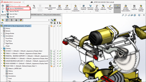
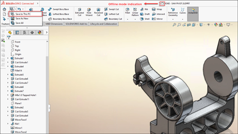
- Save Your Project:
- Save your work frequently to avoid losing progress.
- Start Designing!
- With your project set up and tools at your disposal, unleash your creativity and start designing confidently.
Remember, SOLIDWORKS Pro provides a robust environment for 3D modeling, and by following these steps, you’ll be well on your way to giving your designs a full 3D overhaul!
Advanced Techniques in SOLIDWORKS CAD for Efficient Design
Once you’ve mastered the basics of SOLIDWORKS Pro, it’s time to delve into advanced techniques to enhance your design process.
SOLIDWORKS Pro offers a suite of advanced features tailored for efficiency. These include leveraging assemblies for complex designs, utilizing cut lists and cost estimation, and integrating composite materials. Additionally, SOLIDWORKS Pro provides tips for efficient sketching and 3D modeling, alongside utilizing SOLIDWORKS Premium and CAD integration capabilities. By mastering these techniques, you elevate your designs and optimize the product development process.
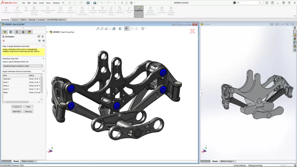
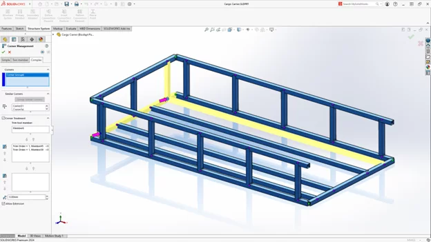
Leveraging SOLIDWORKS Assemblies for Complex Designs
In SOLIDWORKS Pro, using assemblies is a big help! With intelligent tools and features, they can give accurate cut lists, estimate costs, and handle materials like composites. With the cut list feature, you can know exactly how much material you need. Cost tools predict manufacturing expenses. Plus, it’s great for working with cool materials like carbon fiber or fiberglass. You can easily figure out shapes and sizes when they’re flattened.
Simply put, SOLIDWORKS Pro with its assemblies is like having a smart assistant for making complex designs and manufacturing simpler.
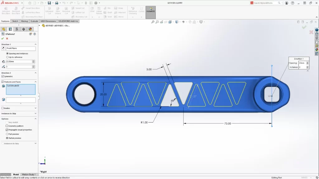
Tips for Efficient Sketching and Modeling in 3D
Designers have access to a range of tools and features that can enhance their sketching and modeling process. Here are some tips for efficient sketching and modeling in 3D using SOLIDWORKS Pro:
- Utilize advanced sketching tools for precise and efficient sketch creation.
- Leverage efficient design iterations and modifications.
- Utilize the comprehensive library of prebuilt 3D CAD models and other CAD data available in Toolbox.
Integrating 3D into Your Workflows
Integrating SOLIDWORKS Pro ramps up your design game and boosts productivity. It’s packed with features that smooth out every design stage, from simulation to documentation.
You get stress analysis tools, stunning visualizations with Visualize, and top-notch documentation. Plus, there’s PDM for file management, automation to speed up tasks, and a toolbox for quick access to CAD models.
Collaborating on Projects
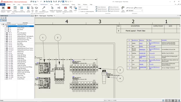
Collaboration is essential in any design project, and SOLIDWORKS Pro nails it with a variety of features. Whether you’re teaming up with engineers, electrical designers, or other stakeholders, it has tools to make collaboration seamless.
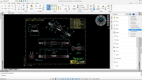
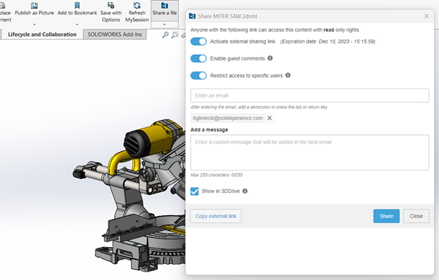
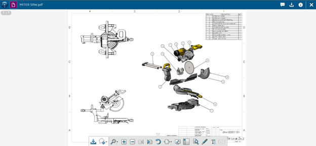
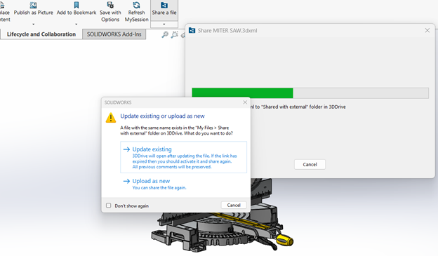
For electrical design, there’s CircuitWorks for ECAD/MCAD data sharing. Plus, there’s eDrawings Professional, making it a breeze to share 3D models and 2D drawings via email. With Pro’s collaboration features, including the ability to design and route electrical wiring, harnessing, cabling, and conduit assemblies in 3D, and the possibility to connect to the cloud-powered 3DEXPERIENCE platform, designers can boost communication, streamline workflows, and elevate the entire design process with additional capabilities for collaborating on projects.
Overcoming Common Challenges in Moving to 3D
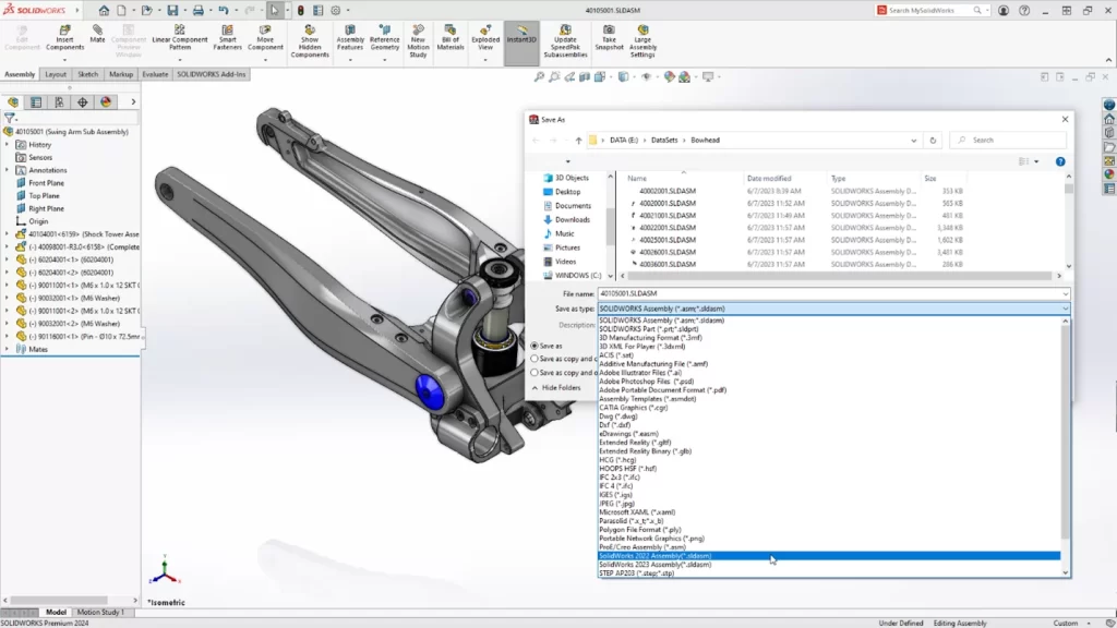
Some common challenges in moving to 3D design include adapting to new software, transferring existing 2D or CAD data to the new system, and ensuring compatibility with other design tools and processes. To overcome these challenges, SOLIDWORKS Pro provides troubleshooting tools for typical issues, strategies for smooth transitioning, and comprehensive support for design engineers.
Strategies for Smooth Transitioning from 2D to 3D
Transitioning from 2D to 3D requires careful planning and execution to ensure a smooth transition. Here are some strategies for smooth transitioning from 2D to 3D:
- Define clear goals and objectives for the transition: Clearly define what you want to achieve with the transition to 3D design and communicate these goals to your team.
- Plan and prioritize: Create a roadmap for the transition process, including a timeline and milestones. Prioritize which projects will be transitioned first based on complexity and impact.
- Provide training and support: Invest in training for your team to ensure they are familiar with the tools and features at their disposal. Provide ongoing support and resources to address any challenges or questions that may arise.
- Utilize built-in tools: Take advantage of tools for data migration, compatibility checking, and performance optimization to ensure a smooth transition.
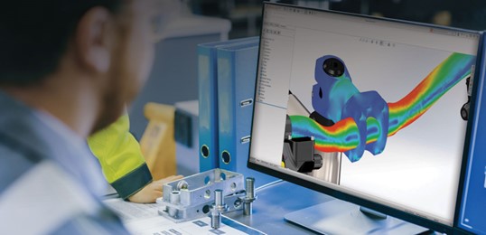
Introduction to Simulation
Simulation is vital for design and SOLIDWORKS Pro, with its compatible add-ins, nail it with a robust set of tools and features for your design environment.
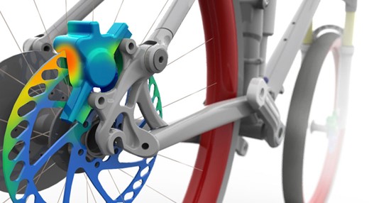
Simulation Standard offers stress analysis, motion analysis, and more, letting designers test their creations in various scenarios. This helps spot problems early, saving time and money on physical prototypes. With simulation features, designers are empowered to make smarter decisions, fine-tune designs for safety and performance, and ensure top-notch results.
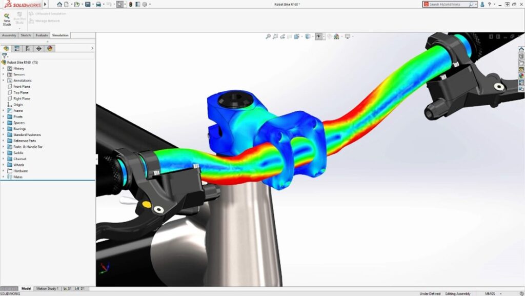
Applying Simulation to Validate Your Designs
Now that you have your simulation data, what do you do with it? Validating designs is key in the design process, and SOLIDWORKS Pro has that covered too! Its purpose-built tools ensure designs meet performance and safety standards.
By running simulations using Simulation Standard, you can analyze stress distribution, evaluate motion behavior, and assess other key factors that impact your design’s performance. Leveraging Simulation allows for informed decisions, reducing design flaws and optimizing performance and efficiency.
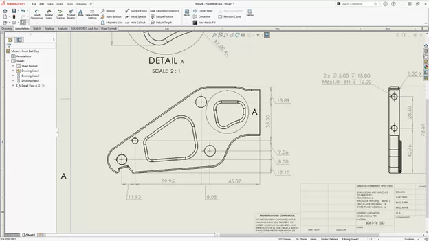
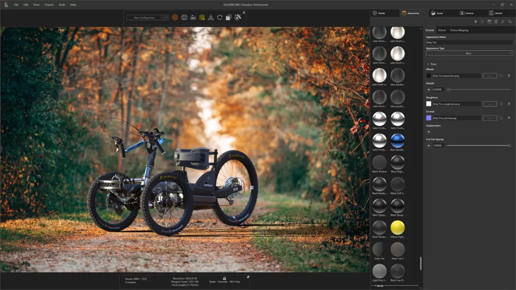
Leveraging Visualize for Realistic Renderings

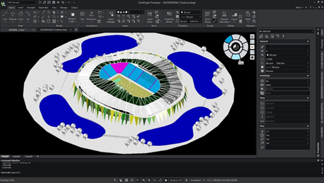
Effective communication relies on visualizing designs. Visualize simplifies the creation of realistic renderings. Designers can effortlessly produce top-tier visual content, enhancing presentations and marketing materials with photorealistic images. Visualize boasts advanced rendering features, including dynamic lighting and realistic textures, which make designs truly stand out. By leveraging Visualize, designers can craft compelling visuals that breathe life into their creations, effectively conveying their vision to stakeholders. It’s a valuable asset for elevating presentations, marketing collateral, and design reviews, ensuring stakeholders grasp the essence of the design accurately.
Conclusion
Transitioning from 2D to 3D design with SOLIDWORKS Pro not only unlocks enhanced product development possibilities but also offers improved visualization, advanced simulations, streamlined workflows, and seamless collaboration. Mastering SOLIDWORKS Pro empowers efficient design creation, while overcoming challenges through troubleshooting and smooth transitioning strategies ensures success.
Frequently Asked Questions
What Are the Prerequisites for Transitioning to SOLIDWORKS?
To transition to 3D design, some prerequisites include a basic understanding of mechanical design principles, familiarity with CAD data management, and a clear understanding of the design process. Additionally, having access to SOLIDWORKS tools and resources is essential for a successful transition to 3D design.

Any questions? Need help? Ask one of our experts.
Whether you’re ready to get started or just have a few more questions, you can contact us toll-free: