This Year’s Top 10 Enhancements in SOLIDWORKS Browser-Based Roles

BLOG

This Year’s Top 10 Enhancements in SOLIDWORKS Browser-Based Roles 

SOLIDWORKS browser-based roles are purpose-built for your needs and include parametric modeling, subdivision (Sub-D) modeling, and much more, and since they run on the 3DEXPERIENCE platform you also get built-in data management and collaboration capabilities that benefit the whole team. The latest enhancements brought in with SOLIDWORKS 2023 for these solutions include 2D drawing improvements, smart mates, and net surfacing, as well as improvements to downstream communication for manufacturing to help you be as productive as possible. 


Let’s have a look at this year’s top 10 enhancements. 


1- 2D Drawings | Manufacturing Definition Creator – Create both 3D definitions and 2D drawings to meet supplier requirements faster. 


Manufacturing Definition Creator easily creates both 3D product manufacturing information (PMI) and 2D drawings. Use either model-based definition (MBD) or 2D sketches to break down the barrier between 3D and 2D and leverage model-based workflows while providing the flexibility needed to preserve existing manufacturing processes and supplier relationships that still use 2D drawings. 


With Manufacturing Definition Creator, you don’t have to create a 2D drawing from scratch, you can use your existing 3D PMI to create a 2D drawing complete with definition, in a matter of a few mouse clicks. 

blog-img

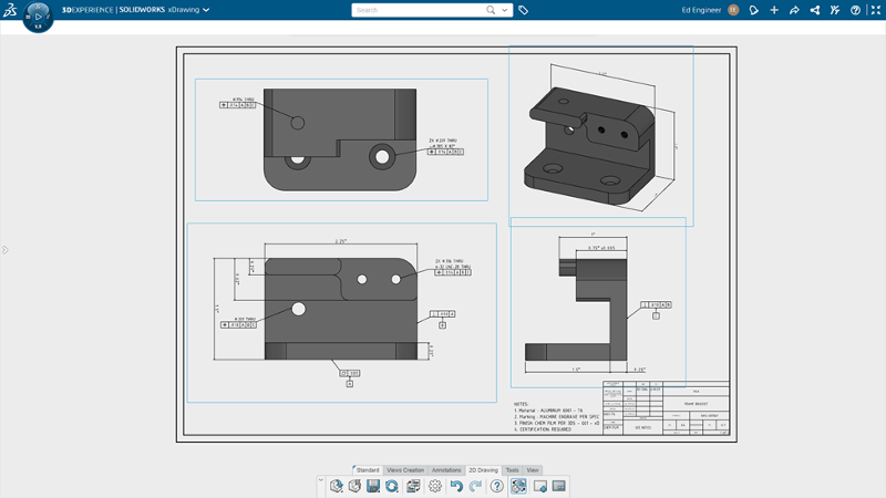
Manufacturing Definition Creator features 3D definition and 2D drawing capabilities. 


2- Welcome App | 3D Creator – Get up to speed on your new solutions quicker with a personalized welcome experience. 


Whether you’re a new or experienced user, the Welcome app in the 3D Creator parametric design role helps you get up to speed, fast. Access the SOLIDWORKS online communities, switch seamlessly between your roles, and explore the Learning Center where you’ll find tips for getting started, in-depth learning tutorials, and Sample Content. Drag and drop a model into your interface to check out the role’s modeling features. 


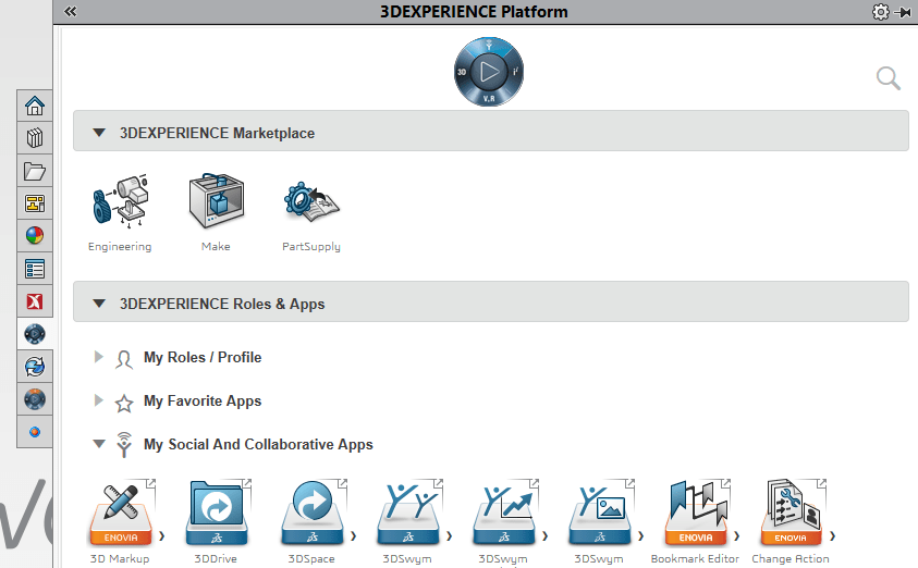
In addition to launching your roles, you can open your collaboration and management apps: 3DPlay, the Bookmark Editor, and more. 

blog-img

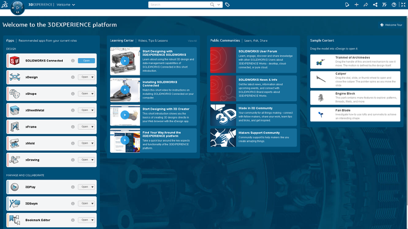
Access key role and app information plus SOLIDWORKS online communities directly in the Welcome app. 


3- Design Assistant Smart Mate with Artificial Intelligence (AI) | 3D Creator – Build assemblies faster. 


Design Assistant Smart Mate is one of the many AI-enabled features that uses built-in machine learning algorithms to offer design guidance based on your workflows. This tool is designed to help you create mates by dragging and holding a component in the position where you want it to mate with the surrounding components. The Smart Mate command will automatically launch when you drag a component close to the edge of another component.

blog-img

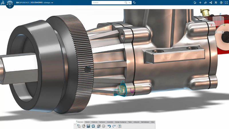
Drag and snap components into place with the Smart Mate command. 


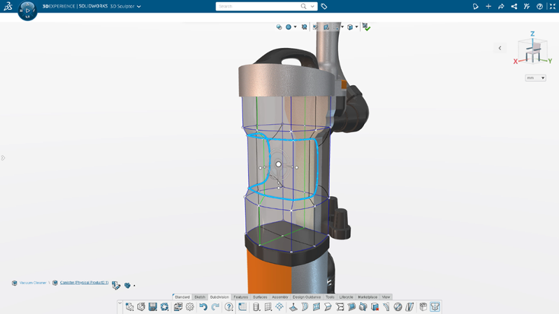
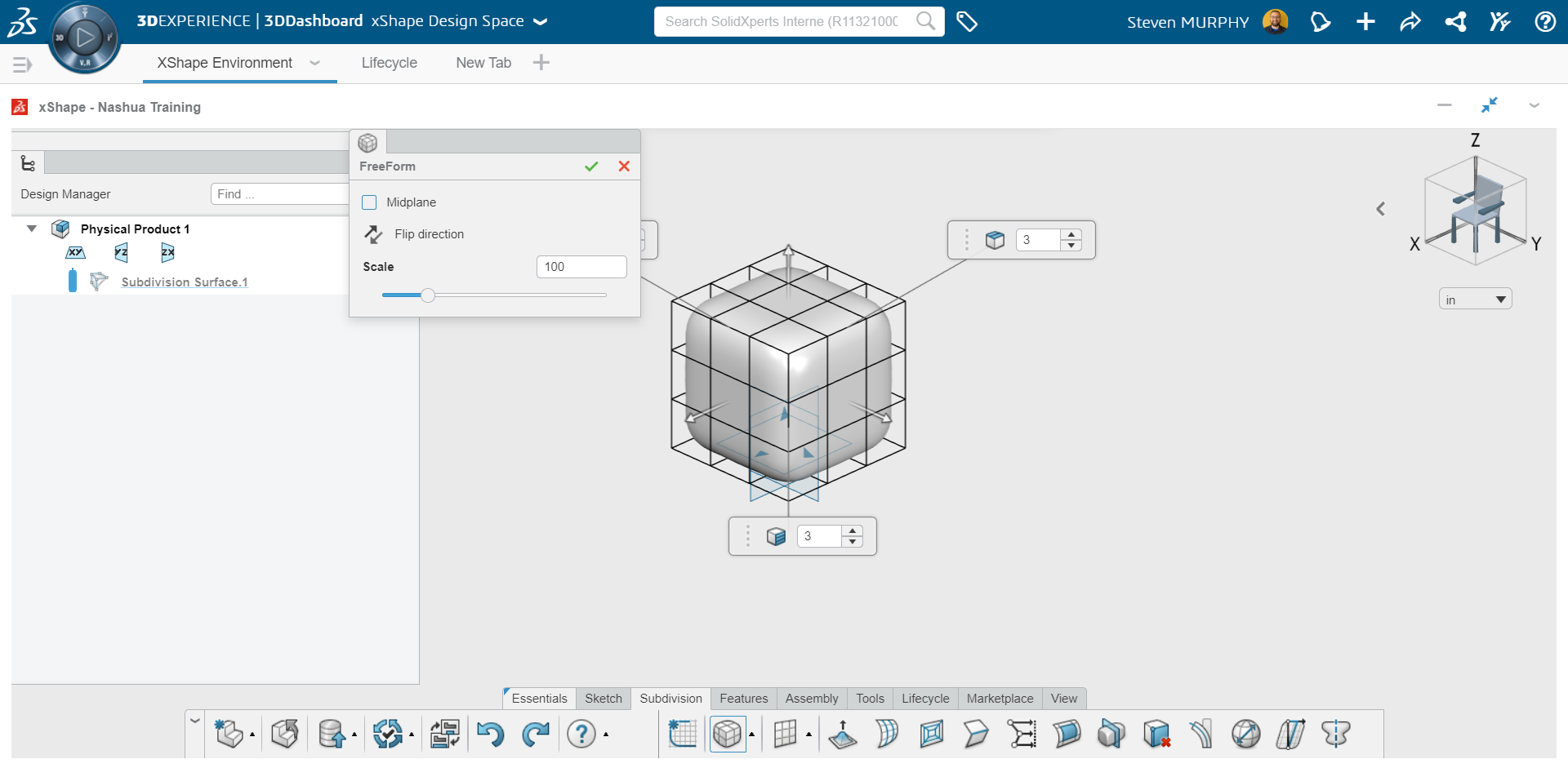
4- Net Surfacing | 3D Sculptor – Create subdivision surfaces using familiar CAD operations. 


Create your own primitives using a loft, a boundary condition, or a sweep with the Net Surfacing Command in the 3D Sculptor Sub-D modeling role. Start by defining a surface using familiar parametric commands, then use freeform Sub-D modeling to modify the shape of your customized primitive. You can also toggle between the customized parametric surface or subdivision surface. To increase design efficiency, choose pre-defined primitives or create your own with the Net Surface command. 

blog-img

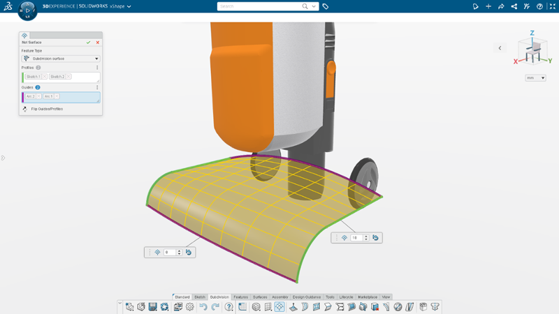
Use familiar CAD operations to create a subdivision surface with Net Surfacing in 3D Sculptor. 


5- 3D Print Orientation and Nesting Optimization | 3D Creator – Automatically set your parts up for success and save time on 3D prints. 


The Print3D feature gives you the option to auto-arrange a selection of parts on the 3D printer build plate. Work smart and let the Print3D feature work hard for you to get the most efficient layout of your assemblies. This feature also helps reduce material costs! 

blog-img

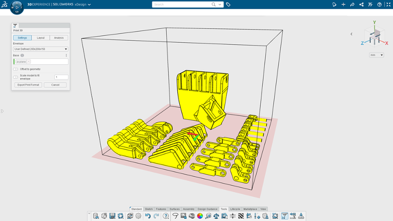
Create the most efficient layout with automatic optimization and nesting and reduce material costs. 


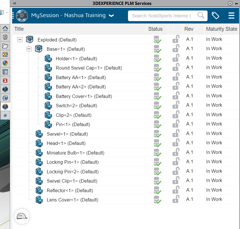
6- OM Tables | Manufacturing Definition Creator – Clearly define your assemblies and provide critical assembly information. 


Easily and efficiently provide the most valuable information with 3D definitions and 2D drawings. Create and include a bill of materials (BOM), and automatically link BOM table values directly with ENOVIA for consistent, up-to-date information. 


Customize your BOM tables using familiar table editing functionality and provide a wide range of linked assembly properties, such as part quantities, revisions, part numbers, and more. 

blog-img

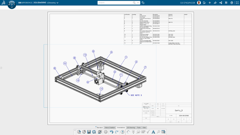
Create a detailed bill of material (BOM) tables for 3D assembly definition and 2D drawings. 


7- Automatic Corner Trimming | 3D Structure Creator – Save time by automating corner trimming processes.   


Create accurate, manufacturing-ready structure designs, and do it quickly with 3D Structure Creator. The Automatic Corner Trims feature enables you to automatically trim members during member creation, so you don’t have to do this after. Create members based on sketch segments, model edges, points, or intersection planes, or between two members, and check Enable Automatic Corner Trims to trim corners and endpoints. 

blog-img

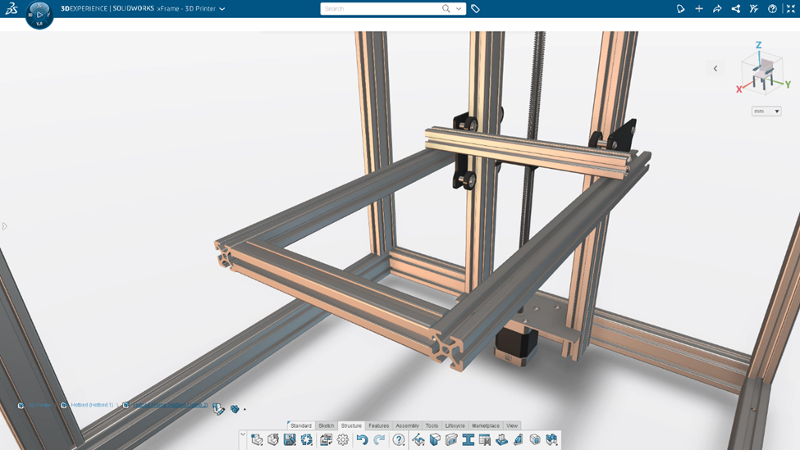
Create structure systems faster by automatically trimming members during member creation with 3D Structure Creator. 


8- Recognize Command | 3D SheetMetal Creator – Increase productivity and create complex sheet metal shapes using traditional modeling features. 


3D SheetMetal Creator features easy-to-use associative parametric sheet metal design tools. The Recognize command, for instance, includes solid and surface options so you can easily create complex sheet metal shapes and reduce complex design workflows. In addition to the “thin” option, you can convert solid bodies and surfaces with automatically generated flat patterns for manufacturing that doesn’t require shelled or uniform thickness geometry. 


You can also customize bends, walls, splits, and gap distances with a single command! 

blog-img

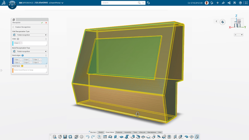
Create complex sheet metal geometry using conventional convert-to-sheet metal workflows in 3D SheetMetal Creator. 


9- Selection Accelerators | 3D Sculptor – Speed up selections and easily shape sub-D mesh. 


There are several new selection accelerators you can access from the context toolbar and by using Shift Select. If you need to select a group of tangent edges or faces, you can use the Select Tangency accelerator on the context toolbar. 


To select edges around the face of a box or quad ball, there’s a Corner Loop accelerator that lets you Shift Select two edges on either side of a corner to select the entire loop, and for creased edges, you can use the Select Crease accelerator on the context toolbar so you can select connected creased edges. Also, shift select will follow along creased edges. 

blog-img

Speed up geometry selection and modifications using new selection accelerators in 3D Sculptor. 


10- Thickness Analysis | 3D Mold Creator – Ensure uniform thickness and improve design integrity by verifying that parts will fill properly. 


3D Mold Creator provides specialized mold tooling design functionality that enables the faster, automated, and more robust design of mold cores, cavities, and inserts. The Thickness Check tool, for instance, enables you to perform thickness checks using a rolling ball “sphere” method or the normal distance “ray” method. You can easily identify thickness ranges using colors, in addition, to manually investigating thicknesses at specific locations by clicking on the area you’d like to investigate. 

blog-img

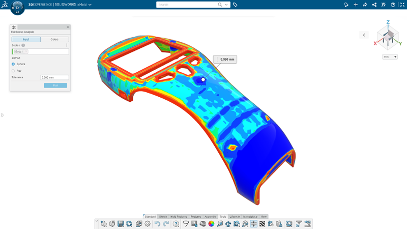
Prevent sink marks by ensuring uniform thickness with the Thickness Check tool in 3D Mold Creator. 


SOLIDWORKS browser-based roles available on the 3DEXPERIENCE platform enable engineers and designers to work more efficiently on designs and assemblies from anywhere in the world. With the release of SOLIDWORKS 2023 hundreds of improvements have been made to accelerate your 3D product design processes. For more information on all the improvements, and to know more about what SOLIDWORKS or 3DEPXERIENCE solutions best fit your workflows, don’t hesitate to contact our Xperts teams

X_green_halo

Any questions? Need help? Ask one of our experts.

Whether you’re ready to get started or just have a few more questions, you can contact us toll-free:

    How 3DExperience will help you use SOLIDWORKS  

    BLOG

    How 3DExperience will help you use SOLIDWORKS

    By Steven Murphy – Elite Applications Engineer

    While the 3DExperience platform takes the CAD industry by storm, what does it mean for the average SOLIDWORKS user? Despite the industry trend toward SAAS (Software as a service), SOLIDWORKS will remain available as a perpetual license. The only change for conventional SOLIDWORKS users is access to a wider variety of tools using the 3DExperience platform to augment your current workflows. Knowing what tools you have access to on the cloud will give you a competitive edge and the tools you need to stay successful.


    Top Tools to Leverage 3DExperience Using SOLIDWORKS


    ENOVIAWORKS (PLM)

    Everyone is familiar with “the cloud,” or the idea of connecting via internet to servers remotely in order to gain flexibility and save on hardware costs. With the integration of ENOVIAWORKS into the 3DExperience platform, cloud PLM [Product Lifecycle Management] services are readily available to use with SOLIDWORKS files. This includes a complete product data management (PDM) system as well as tools to manage the processes surrounding the part’s fabrication.

    For the average SOLIDWORKS user, this means access to revision controlled files from anywhere you can use SOLIDWORKS. Just login to the PLM services pain integrated with SOLIDWORKS and you are off to the races. You can also drag and drop files from the 3DExperience platform into SOLIDWORKS to open and start working. On top of this functionality, the files in PLM can be referenced in chats, integrated into blog posts, and worked with in the 3DExperience “X Apps.” These X Apps provide a range of versatility for part creation without ever leaving the cloud.


    3DEXPERIENCE PLM SERVICES SOLIDWORKS View


    XShape

    XShape is the premier SubD cloud application available on the 3DExperience platform. Many industrial designers know the challenge of replicating complex surfaces inside of any CAD package. XShape allows for the creations of surfaces and parts using push-pull manipulation of primitive shapes while maintaining continuity. This functionality greatly surpasses the ability of SOLIDWORKS Freeform to create your aesthetically pleasing complex surfaces with your CAD file. On top of that, the SOLIDWORKS integration means that you can drag and drop the files from your web browser right into your model.

    If you are doing any surfacing, industrial design, or non- parametric modeling, this application is a must have. Because this application was developed with SOLIDWORKS in mind, the seamless transition between software will support your workflow.


    XShape SubD Modeling


    3DExperience Marketplace

    Who knew that you have access to quality industrial suppliers worldwide within SOLIDWORKS itself? You can find the manufacturers that your product needs without having to spend time and effort creating your own supply chain. This especially powerful in an industry where rapid prototyped 3D printed parts are becoming the de facto standard. Directly integrated with your SOLIDWORKS model, you can get competitive pricing, see shipment costs, and determine which provider meets your deadline.


    The 3DExperience Marketplace is located in the “3DExperience Platform” add in located in SOLIDWORKS which provides the flexibility that any engineer can take advantage of. Let Dassault Systèmes qualify the manufacturers for you, all you need to do is provide the model!


    3DExperience Marketplace Within the Task Pane


    The 3DExperience brings value to all conventional SOLIDWORKS users, expanding the tools available to bolster your workflow. The platform provides you with the ability to create new types of models, store and access data online, as well as easily identify manufacturers based on your requirements. From here, the Dassault Systèmes ecosystem will only continue to adapt and grow.


    Interested in the 3DExperience Platform? Reach out to our Xperts anytime with any questions or for more information.

    X_green_halo

    Any questions? Need help? Ask one of our experts.

    Whether you’re ready to get started or just have a few more questions, you can contact us toll-free:

      How to add the Thickness of Sheet-metal as gauge in a Layout

      BLOG

      How to add the Thickness of Sheet-metal as gauge in a Layout

      In this tech tips we are going to find out how to add the Thickness of Sheet-metal as a gauge in a Layout:

      When one designs products with sheet metal, the industry uses the thickness values from a gauge table. For example, an 18 gauge is equivalent to a thickness of 0.0359 for a steel part. It is possible to use this kind of table in the sheet-metal function of Solidworks.

      Continue reading “How to add the Thickness of Sheet-metal as gauge in a Layout”

      Enhancements in PropertyManager in SOLIDWORKS Simulation

      BLOG

      Enhancements in Remote Loads/Mass PropertyManager in SOLIDWORKS Simulation

      By Sakineh Orangi – Simulation Application Engineer at SolidXperts

      In SOLIDWORKS 2019, the Remote Load/Mass PropertyManager was redesigned to improve the user experience and it introduced distributed coupling. The Remote Loads/Mass PropertyManager allows us to apply remote loads, remote masses, and remote displacements for static, topology, and nonlinear studies. One of the ways to access the Remote Loads/Mass PropertyManager is to right-click on External Loads in the simulation tree of linear static, nonlinear static, or topology.


      We select the faces to apply remote loads, remote masses, or remote translations and/or rotations.


      We define the coordinate system used for the interpretation of the location and directions of the remote features.


      After this step, we enter the coordinates of the reference node location in a local or global coordinate system.


      In the case of the definition of remote force or remote distance, we check the Translational Components and enter the values of remote loads or remote translation in the three directions X, Y, and Z.


      If there are any remote moments or remote rotations, we check Rotational Components and then enter the data.


       data-lazy-src=


      Learn more about everything new in SOLIDWORKS from 2015 to 2019 by downloading our White Paper.

      To learn more about SOLIDWORKS Simulation, click here.
      X_green_halo

      Any questions? Need help? Ask one of our experts.

      Whether you’re ready to get started or just have a few more questions, you can contact us toll-free:

        Better integration of SOLIDWORKS Electrical for SOLIDWORKS PDM

        BLOG

        Did you know that a better integration of SOLIDWORKS Electrical for SOLIDWORKS PDM is now available?

        SOLIDWORKS provides you with a new tool: SOLIDWORKS Electrical integration for Professional SOLIDWORKS PDM 2018. SOLIDWORKS Electrical Integration for SOLIDWORKS PDM is a new SOLIDWORKS Electrical component that implements a better integration with SOLIDWORKS PDM Professional.

        SOLIDWORKS Electrical Integration for SOLIDWORKS PDM is a free product that will be available to customers using SOLIDWORKS Electrical 2D and SOLIDWORKS PDM Professional.

        SOLIDWORKS Electrical Integration for SOLIDWORKS PDM is being released with SOLIDWORKS Electrical 2018
        The most important functionalities of this tool are:

        • SOLIDWORKS Electrical users will obviously be able to store their projects in SOLIDWORKS PDM from within SOLIDWORKS Electrical.
        • Allow the work-sharing between users.
        • Variable mapping between both products so that key electrical metadata can be made available in SOLIDWORKS PDM.
        • Electrical components libraries will be pushed and synchronized to SOLIDWORKS PDM
        • “Where Used” information will be available.
        • This product will also manage electrical deliverable files, such as PDF and DWG.
        • It will also publish an advanced electrical Bill of Material (BOM) to SOLIDWORKS PDM.

        Installation, administration and users guide will be installed in the installation folder of SOLIDWORKS Electrical integration for Professional SOLIDWORKS PDM 2018.

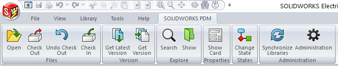
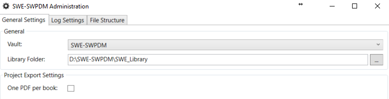
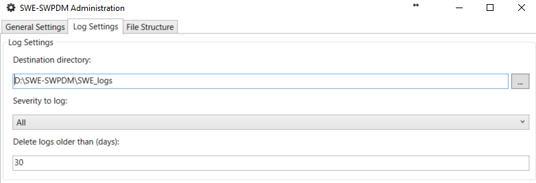
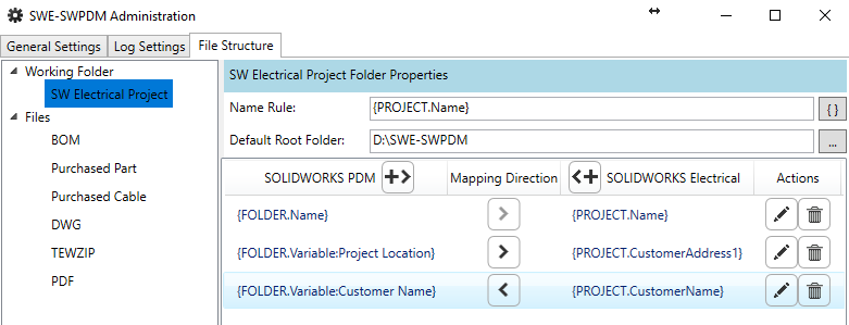
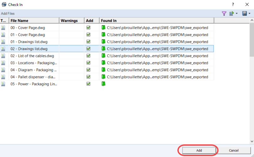
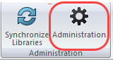
        Once SOLIDWORKS Electrical integration for Professional SOLIDWORKS PDM 2018 was installed in SW Electrical, you must define some parameters in the administration of the tool.


        You will beforehand have created a folder structure in your PDM vault to host your 2D SW Electrical projects, and logs, as well as a Library folder for synchronization of SW Electrical.

        In the tab General Settings:
        Choose your Vault and the library folder in your vault.

        In the tab Log Settings:
        Define the folder of logs inside the vault, as well as its options.

        In the tab File Structure:
        According to SOLIDWORKS Electrical document types, you can make some Mapping.

        To start the collaboration of SOLIDWORKS Electrical integration and SWPDM.
        Since you are Project Manager:
        Unarchive and open your SW Electrical project
        (Files *.tewzip)

        Work on your project as usual, when ended.
        Make a synchronization of your library towards PDM,
        by using Synchronize Libraries.

        And make Check-in:

        As asked, select the parent file of your project.

        A table showing all the files which will be archived will appear, click Add.

        Let the process make the creation of all the objects of your project (it can take some time).

        Once the process is completed; you will notice that the structure of your project SOLIDWORKS Electrical was duplicated in PDM. by adding a folder BOMS.
        and creating a .pdf file of your complete drawing package.

        SOLIDWORKS Electrical

        Local PDM view

        SOLIDWORKS Electrical


        Local PDM view

        You will also notice the creation of all your drawings in .dwg format.

        All the PDM tabs will be accessible. You can even design a specific card for your SOLIDWORKS Electrical projects.

        As well as file cards which will inherit some properties of their folder card.

        In the folder BOMS; you will find all the bills of material for your project. It will be possible for you to open and export your BOM throw Excel such as any other BOM in PDM.

        By choosing a file of a BOM (Click + right button of the mouse) to obtain the options such as: Browse to, allowing to go to the localization of the library parts.

        This new tool will allow better collaboration between your electric and mechanical engineering departments. If you have any questions just contact one of our Xperts.

        On the same subject, take a look at the video produced by SOLIDWORKS:

        X_green_halo

        Any questions? Need help? Ask one of our experts.

        Whether you’re ready to get started or just have a few more questions, you can contact us toll-free:

          Third-party Files Available for Import as Graphics Bodies

          BLOG

          Third-party Files Available for Import as Graphics Bodies

          By Gregory Bejtlich – Application Specialist at SolidXperts

          Following the release of SOLIDWORKS, users can now import third-party files as graphical 3D meshes rather than solid or surface bodies. Previous releases were limited to the mesh file types *.stl, *.obj, *.off, *.ply, *.ply2. Changes for 2019 also include the addition of a ‘Graphical Body’ check box from the ‘Open’ dialog.

          Importing as a graphics body can be very useful for manual remodeling or taking specific measurements. Additionally, importing as a graphics body utilizes significantly fewer resources when opening large or complex files.

          To access this feature, follow the steps below.

          Import as a Graphical Body can be accessed with File > Open (Ctrl + O) or Insert > Component > Existing Part/Assembly within an assembly.

          Using the file format drop list, select any third-party format such as Autodesk Inventor (*.ipt) or ProE/Creo (*.prt)

          Unlike importing mesh files, users are no longer required to enable the Graphics Body through the options menu. SOLIDWORKS now includes an “as Graphical Body” check box below the file explorer. Select the check box and click ‘Open’.

          The Inventor Part (*.ipt) is now imported as a Graphical Body. Notice the feature tree displays the part not as a surface body or solid body – but as a Graphic Body.


          Contact Us if you have any questions.

          X_green_halo

          Any questions? Need help? Ask one of our experts.

          Whether you’re ready to get started or just have a few more questions, you can contact us toll-free:

            How to fix a toolpath with SOLIDWORKS CAM?

            BLOG

            How to fix a toolpath with SOLIDWORKS CAM?

            By Ghyslain Lacombe – Application Specialist at SolidXperts

            When creating a toolpath, the result can sometimes not be the one you want. In the following example shown in video and screen captures, there is a steel island in the center of a cutting.
            How to correct the default toolpath in order to remove the steel island left by the initial toolpath?

            1- Region to be machined:

            As you can see, the customer wants to machine this region:


            2- Result of the initial toolpath:


            The result of the toolpath leaves an undesirable steel island: How to correct this?

            3- Edit the function: Z Level:

            The operation parameters are as follows:


            4- In this case, you must change the method from constant to scallop to be able to eliminate material that cannot be machined with the other process.


            5- The result still leaves an unmachined region because it is necessary to increase the precision:


            6- It is then necessary to reduce the scallop and the minimum cut amount to be able to remove all the material.


            7- The result shows that the machining is now complete:


            Therefore, depending on the kind of workpiece, you must determine the machining method to use and adjust the number of passes and the scallop for machining to be complete.

            Contact Us if you have any questions.

            X_green_halo

            Any questions? Need help? Ask one of our experts.

            Whether you’re ready to get started or just have a few more questions, you can contact us toll-free:

              Hidden Keyboard Shortcuts for SolidWorks

              BLOG

              Hidden Keyboard Shortcuts for SolidWorks

              As with video games, there are hidden shortcuts in the SolidWorks software. Today, we reveal some of these different combinations to help with your part, assembly, and drawing creation.

              Continue reading “Hidden Keyboard Shortcuts for SolidWorks”

              Server Installation for SOLIDWORKS PDM Standard

              BLOG

              Server Installation for SOLIDWORKS PDM Standard

              By Elene Teolis – PDM Application Specialist

              The following steps will guide you through the installation of SOLIDWORKS PDM Standard and its basic minimal operational configuration settings.

              This document will cover the following points:

              1. Server Preparation
              2. Software installation
              3. Archive Server Configuration
              4. License Activation
              5. Creating a Safe

              Server Preparation

              1.1. Ensure the server meets the computer requirements. See Hardware and System Requirements – PDM STD.
              1.2. Have your PDM Standard License Number on hand.

              SOLIDWORKS PDM licenses must be released by SOLIDWORKS in order to be activated on a server.

              Contact SolidXperts Technical Support to have your PDM Standard license released.
              -Telephone: 1-877-824-3379 or 1-877-876-5434, ext. 150
              -Email: support@solidxperts.com

              The installation files for PDM Standard can be found on the DVD or in the SOLIDWORKS Portal.

              Software Installation

              2.1. Run ‘Setup.exe’ as an Administrator


              2.2. Choose which Server Products to install

              • Install SOLIDWORKS PDM Server Components
              • Install SolidNetWork Licensed Manager

              2.3. SNL Server Options

              • Enter your license numbers into SolidNetWork License Manager

              SOLIDWORKS PDM Standard licenses are floating. The available number(s) must be entered in this field, separated by a comma.

              2.4. Component Installation Summary

              • SOLIDWORKS PDM server – Edit

              • Validate and/or edit the options for:
                • Server Product: Choose SOLIDWORKS PDM Standard
                • Features to install:
                  • Archive Server
                  • Server Database
                  • Client

                • SQL Server:
                  • Choose the previously installed SQL Express instance
                  • Enter the SA username and password, chosen when installing SQL Express

              2.5. Validate the information – Install now


              Archive Server Configuration

              Once the server component installation is complete, the Archive Server Configuration tool starts automatically to continue configuration.

              3.1. You must change the location of the archive server files so that they are located on the disk intended for the data (as prepared in the first section “Server Preparation”).


              3.2. Choose a password for the default Admin user


              3.3. Choose a password the SA user will need to connect to SQL.

              3.4. Keep administrators only for “Administrative access” and keep the default options for “Attach access”.

              The Archive Server configuration is complete.

              License Activation

              4.1. Start SolidNetWork License Manager


              4.2. In the “Server Administrator” tab, choose “Edit”


              4.3. Choose “Select All”


              4.4. Choose “Activate/Reactivate” your product licenses


              4.5. Validate the information of your License Server

              • The ports are: 25734 and 25735

              Create a Safe

              5.1. Start the PDM Administration tool


              5.2. Right click on the server name – Create a new safe


              5.3. Enter a name for the safe


              5.4. Keep the default values for the location of the archive files.


              5.5. Select the SQL instance created for PDM Standard installation, leave the suggested name for the database.


              5.6. Add the License Server: Enter Port 25734@”name of your server”


              5.7. Choose a default language


              5.8. Check the default password (the password used will be the one set when installing the PDM Archive Server).

              (Uncheck the option and choose a new password if you do not want to use the default password)

              5.9. Choose Quick Start for SOLIDWORKS

              • You will have data cards and a basic workflow among others.

              5.10. Leave all the options checked by default

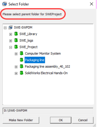
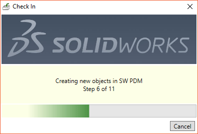
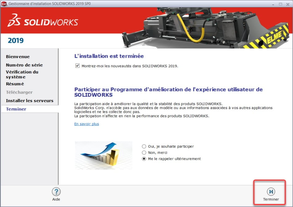
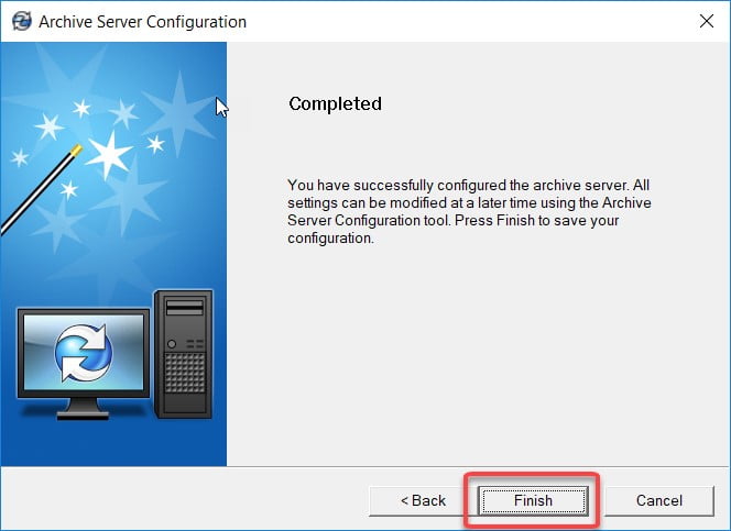
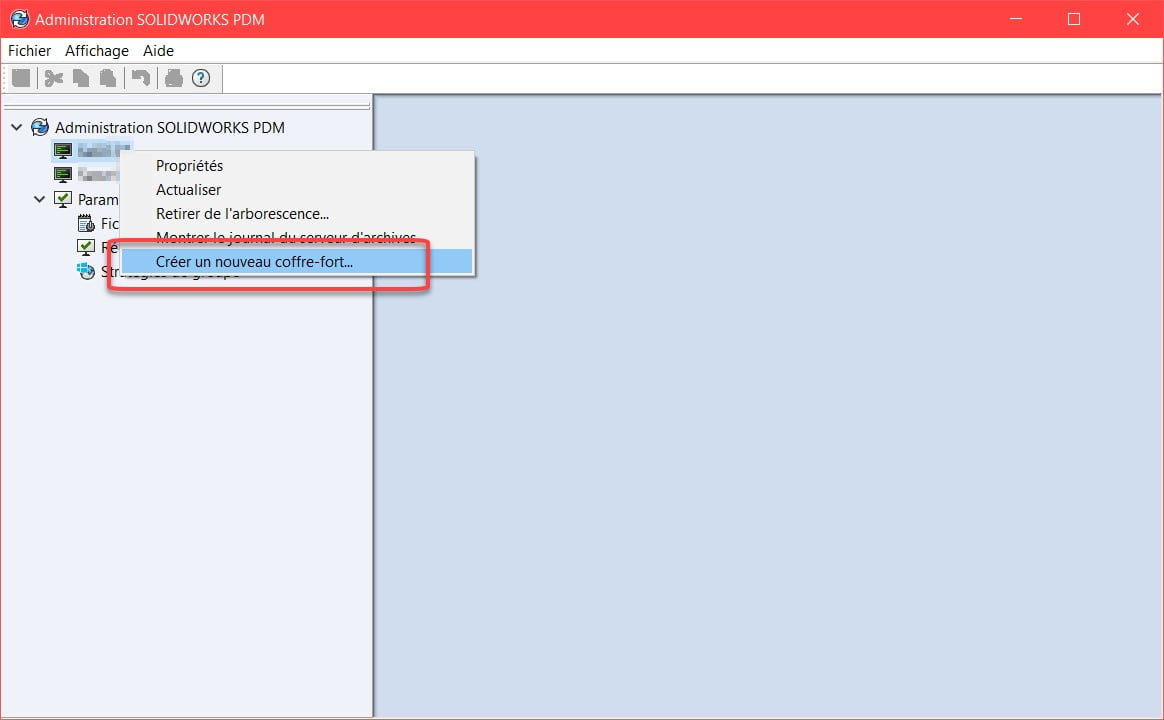
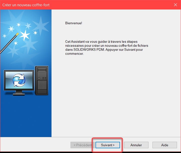
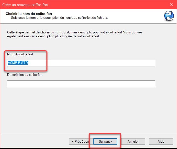
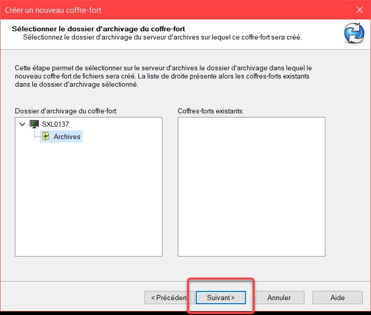
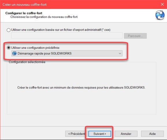
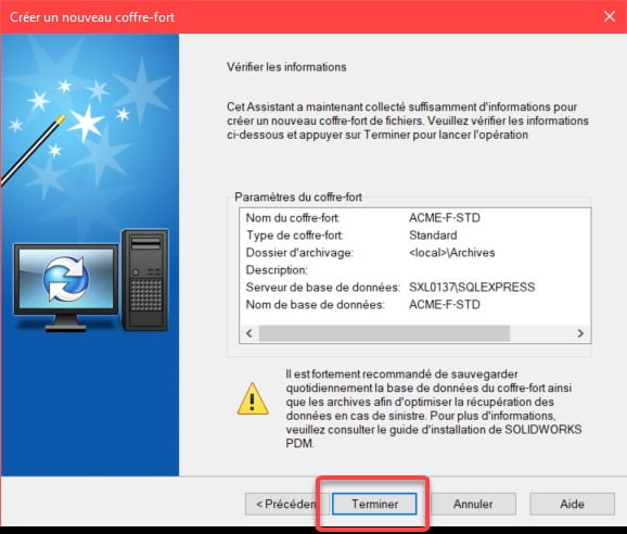
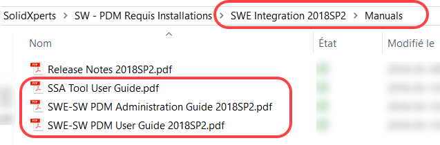
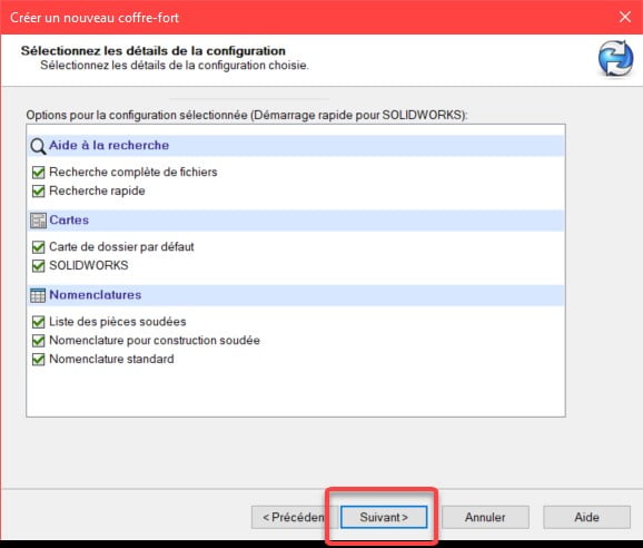
              5.11. Click on “Finish” to create the safe.

              The creation of the safe is finished.

              5.12. The name of the vault now appears in the PDM Administration Tool. Right-click on the server name and refresh if the name does not appear.

              For a standard PDM vault, the vault symbol appears in grey.

              You are now ready to create a local view on the client workstation and start working with your new PDM Standard vault.

              X_green_halo

              Any questions? Need help? Ask one of our experts.

              Whether you’re ready to get started or just have a few more questions, you can contact us toll-free:

                SQL Express Installation and Configuration Guide

                BLOG

                SQL Express Installation and Configuration Guide

                By Elene Teolis – PDM Application Specialist at SolidXperts

                How to Install SQL Express in Preparation for Installing SOLIDWORKS PDM Standard
                *Your windows and menus may vary slightly depending on the server operating system.

                1. Server Preparation
                1.1. Make sure the server meets the technical requirements: View SOLIDWORKS and SW PDM System Requirements
                Make sure that .NET Framework 3.5 and 4.0 are installed, if necessary, configure the “Application Server” role on the server:

                1.2. Prepare file structure
                – If possible, create 2 partitions. Reserve the C: drive for applications and another for the data.
                – Create a folder structure in the disk to receive the data as specified below:


                Suggested file structure

                *SQL cannot save its data to an external disk or hard disk storage (NAS or SAN).

                2. SQL Server Express Installation
                The installation of SQL Server Express is done by following the instructions in the PDM installation guide. Here are the steps followed for a typical SolidXperts installation.
                – SQL Express can be found on the DVD or in SOLIDWORKS downloaded files.

                2.1. Start the installation as an administrator.

                \SOLIDWORKS 2019 SP0\PreReqs\SQLServer\sqlexpr_x64_enu.exe

                2.2. Choose a new installation.


                2.3. Accept the license terms.


                3. Option Selection: Choose Database Engine Services.


                4. Instance Configuration
                – If it is a new installation, choose Default instance.
                – If SQL is already installed, choose Named Instance and enter a name.


                4.1. Server Configuration: Leave default values for service account names.


                4.2. Database Engine Configuration
                – Select Mixed Mode.
                – Create a password for the SQL System Administrator.
                – Specify the SQL Administrator à Click Add Current User and add the Domain Administrators group (domain admin) and/or the local Administrators group.


                – Change the following directories to conform to the file structure created in the server preparation step.


                – Start the installation by clicking on Next.

                Installation complete


                5. SQL Express Configuration
                5.1. Launch ‘SQL Express Configuration Manager’

                – In IPAll, clear the value in Dynamic TCP Ports.
                – Set the TCP Port to the static port number that you want the SQL Server Express instance to follow:

                • If SQL Express is the only SQL Server instance on the system, set the port to 1433.
                • If there are other SQL Server instances on the system, set the port to a single value, for example 1440.

                – Restart the SQL Server Service for the new instance.


                The server is ready to install SOLIDWORKS PDM Standard.


                With 25 years of experience and more than 250 certifications, SolidXperts teams can help you become true 3D experts! An additional question? Need information?

                Contact us! 

                SolidXperts team is always there for you!

                X_green_halo

                Any questions? Need help? Ask one of our experts.

                Whether you’re ready to get started or just have a few more questions, you can contact us toll-free:

                    Download

                      Download

                        Download

                        All search results