AI may not be perfect yet, but it’s precisely why you should start using it today.
 We’ve grown used to talking about artificial intelligence as if the story began in 2022. ChatGPT arrives, the public adopts it, and suddenly AI becomes a topic of casual conversation. But if we want to properly understand what’s happening, we must not confuse media frenzy with historical reality. OpenAI did release ChatGPT publicly (“research preview”) on November 30, 2022, and yes, it was a real social inflection point.
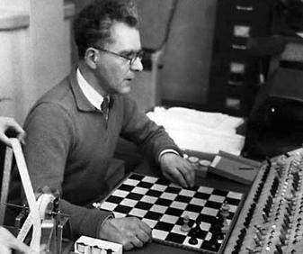
But AI as a field is much older. Turing formalized the intellectual framework of the “imitation game” as early as 1950, and the Dartmouth Proposal (1955) explicitly announced a summer 1956 project dedicated to “artificial intelligence.” Some early demonstrations also appeared quickly: the Ferranti Mark I ran a limited chess program in 1951 (mate-in-two).
This reminder is not meant to give you a history lesson. It serves one purpose: AI is not a feature. It is a trajectory.
And it resembles another well-known human trajectory: that of fire.
The Fire Analogy: Understanding a Technology We Don’t Yet Understand
At this point, you’re probably thinking: “What is he talking about?” Stay with me.
One day, in a cave, one of our ancestors discovered fire. At first, this discovery served very specific purposes: heating, lighting, protection. These were not “industrial innovations”; they were immediate uses. And yet, the full chain – metallurgy, machines, steel industries – that followed from this same discovery reshaped modern history. The human on day one could not imagine the human of today. Not because they were less intelligent, but because they lacked perspective.
We are at the same stage. Except instead of holding a torch, we are writing prompts. And the typical mistake in 2026 is judging AI based on what it is today, as if it were representative of tomorrow’s trajectory.
The Real Signal: Speed of Evolution
What matters is not only what AI does today. What matters is how fast it improves. To make that speed tangible, a cultural artifact has emerged: the “Will Smith Eating Spaghetti test,” now documented as an informal benchmark.
Case Study: The “Spaghetti Test”
In its 2023 version, human motion is unstable: faces and hands deform, physics is not believable. In the 2026 version, the result becomes coherent enough that the difference is obvious: we are no longer looking at a “grotesque meme,” but at a rendering that requires a critical eye to detect AI involvement.
What matters here is the underlying learning dynamic. The progression observed between 2023 and 2026 cannot be attributed solely to model improvements. It is also the result of user adoption.
Early uses produced low-quality, unstable, and difficult-to-use outputs. However, these experiments helped gradually identify model limitations, refine interaction methods (prompts, iterations, post-processing), and structure more robust practices.
In other words, the improvement in outputs in 2026 is inseparable from the learning accumulated by users over time. Current performance is not only technological; it is also cognitive and methodological.
This is how the concept of cumulative advantage should be understood: it does not rely solely on access to technology, but on the experience gained by using it under imperfect conditions.
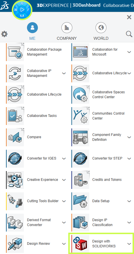
From Internet Culture to the Engineering Office: Why SOLIDWORKS Is Concerned
The transition from “spaghetti → SOLIDWORKS” is not arbitrary. It is the same mechanism applied in a different context. A general-purpose technology crosses a threshold, then infiltrates products, becomes invisible, and ultimately reshapes practices.
We’ve already seen this in the 2010s: AI did not “look like ChatGPT,” but it was already embedded in everyday life. Google Maps, for example, deployed models (including graph neural networks) at scale for ETA (Estimate Time of Arrival) and traffic prediction. The result: you use AI without thinking about it. The advantage rarely comes from an “AI button,” but from the routines that evolve around your activity.
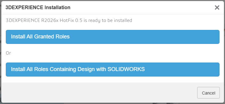
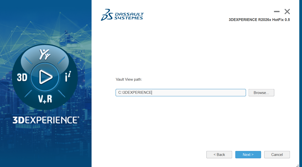
SOLIDWORKS 2026: The AI Shift Is Underway
This is exactly the same dynamic in SOLIDWORKS.
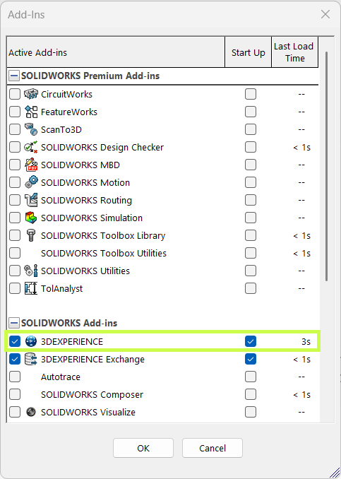
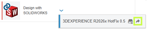
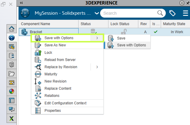
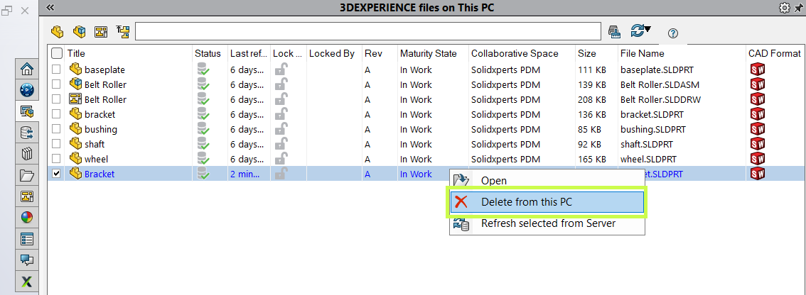
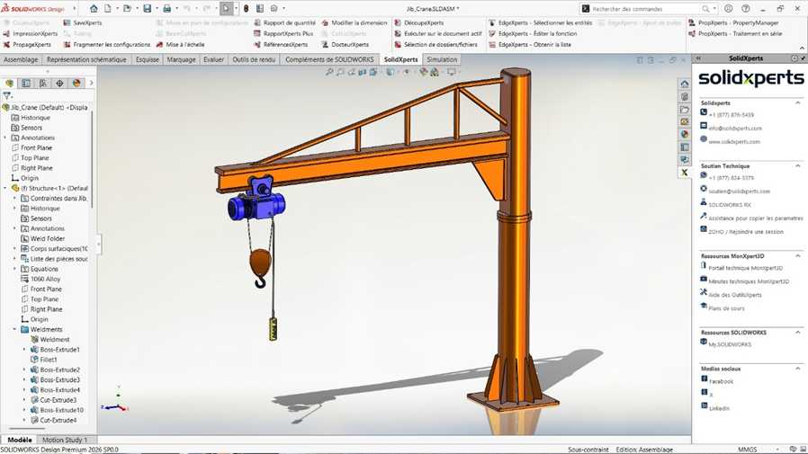
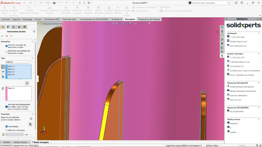
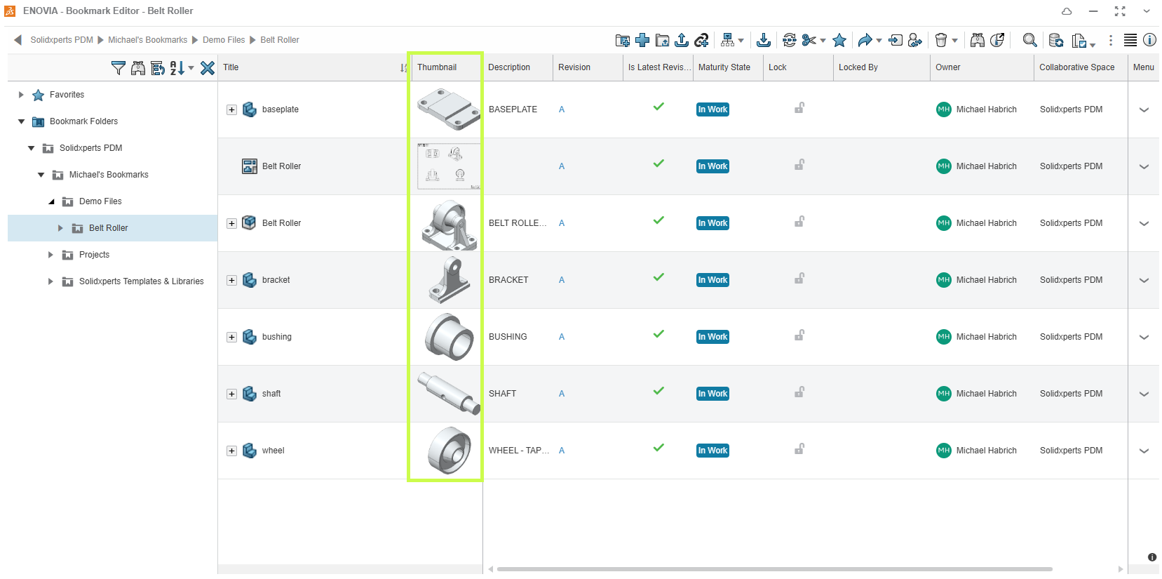
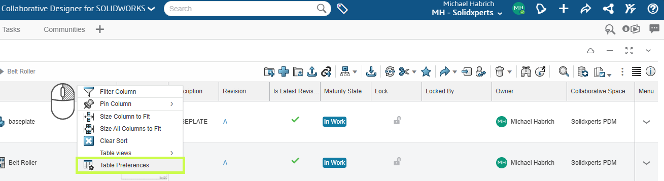
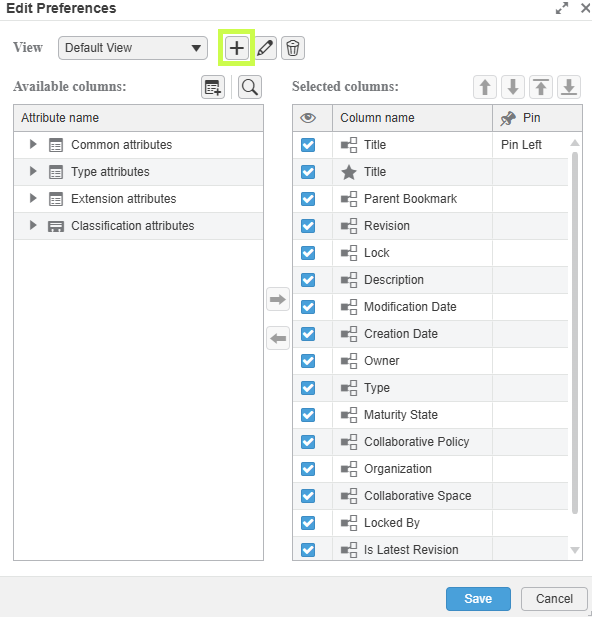
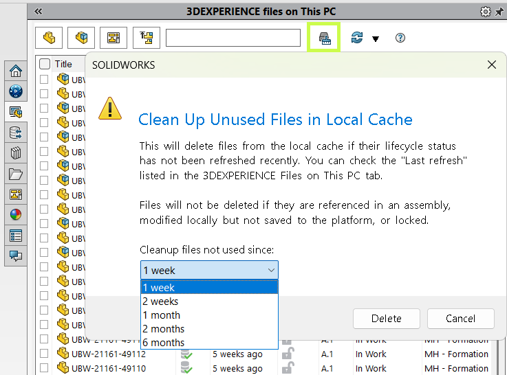
SOLIDWORKS 2026 already integrates AI into areas where real time is lost: drawings, assemblies, and access to knowledge. Dassault Systèmes presents SOLIDWORKS 2026 as an “AI-powered” portfolio (design, collaboration, data management).
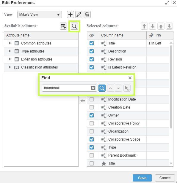
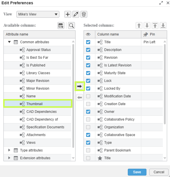
A clear example: Auto-Generate Drawings (BETA). The “What’s New in SOLIDWORKS 2026” documentation explicitly describes automatic drawing generation, including section views and hole callouts.
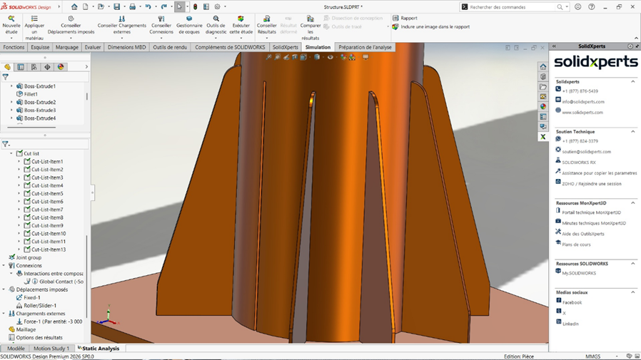
The same logic applies to assemblies: SOLIDWORKS documents AI-based fastener recognition to automatically create SmartMates, with explicitly listed limitations. This level of detail is precisely what makes the promise credible (and reminds us that this is not “magic,” but engineering with constraints).
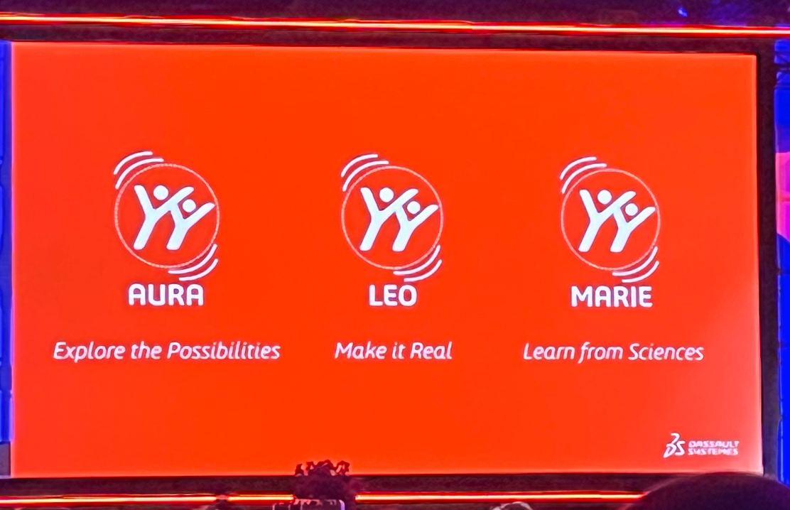
Rather than listing every available feature, it is more relevant to focus on the direction: Dassault introduces “Virtual Companions” (AURA, LEO, MARIE), with AURA and LEO already available and MARIE announced soon. SOLIDWORKS also highlights “AI-guided” features in FD01 (guided analysis, guided creation).
What matters here is not proving that everything is ready. It is recognizing that AI has entered the tool, meaning the learning process has begun, whether you like it or not. And it is moving fast.
Waiting for Maturity: A Strategic Mistake
Let’s be clear: in 2026, all of this is still imperfect. And that is normal. We are at the “spaghetti 2023” stage of AI-assisted CAD: promising, functional in certain areas, but not yet obvious everywhere.
The instinctive reaction for many teams is: “we’ll wait until it’s mature.”
This reaction is human. But strategically, it is a serious mistake.
In 2025, we clearly entered a phase of mass adoption. Nearly 88% of organizations report using AI in at least one function, compared to 78% the previous year. This adoption is accelerating and follows an exponential curve.
From an economic perspective, the signals are just as clear. The generative AI market reached nearly $60 billion in 2025 and could exceed $400 billion by 2031.
In industry, the shift is already visible: nearly 76% of manufacturing companies are using AI in 2026.
But the most interesting point is not adoption. It is the gap between adoption and impact. Despite massive investments, only about 5% of companies currently manage to generate significant value from AI. In most cases, projects remain stuck at the experimental stage, and the majority of initiatives never reach production.
In other words: everyone has access to AI, but very few truly know how to use it. So “waiting” does not mean being cautious. It means allowing a capability gap to form. Because knowing how to use AI is a skill. And it must be learned.
What Research Says About Gains (and Their Limits)
To address the assumption “we’ll wait until AI is ready,” it is important to understand a key nuance: AI does not deliver uniform gains, and that is precisely why early learning matters.
The operational conclusion is simple: early adoption is not a blind bet; it is a mapping phase. It helps you understand when AI works, when it fails, and most importantly how to control it.
What It Really Changes: Redefining Engineering Performance
This is where the thesis becomes concrete: AI will not replace you. A competitor who masters it will.
And I mean mastery in the strict sense. Asking ChatGPT for a carbonara recipe does not count. We are talking about work practices, standards, quality control, understanding when AI accelerates a task and when it introduces risk, knowing where to integrate AI in a project without breaking traceability, and knowing how to train teams without creating blind dependency.
In other words, mastery is not built when the tool becomes “perfect.” It is built while it is imperfect, because that is when you establish your standards, your checklists, your controls, and your best practices.
Ultimately, the value of an engineer will not only be their technical skill. It will be their ability to amplify that skill with properly framed AI.
Conclusion: From Intention to Action
The question is no longer whether you are using AI. It is already present in your tools, your processes, and your competitive environment.
The real question is whether you are learning to use it properly.
Like all major technological transformations, the advantage does not go to those who wait for everything to stabilize. It goes to those who start while it is still imperfect, who experiment, who structure, and who gradually build solid methods.
AI does not replace engineering. It redefines its standards.
And this transition does not happen alone.
At solidxperts, our teams are already working with these tools on a daily basis. We support companies in implementing practical AI use cases in SOLIDWORKS: identifying relevant use cases, integrating them into existing processes, training teams, and establishing reliable standards.
If you want to understand concretely what AI can bring to your environment, we offer demos and working sessions tailored to your reality.
The simplest next step is to start the conversation.


Any questions? Need help? Ask one of our experts.
Whether you’re ready to get started or just have a few more questions, you can contact us toll-free: