We are excited to announce the release of SolidSteel parametric for SOLIDWORKS version 6.0, which brings a wealth of new functionalities and significant improvements to streamline your structural steel design workflow. This latest update is designed to enhance your productivity and simplify your design process with new tools and refined features.
What makes SolidSteel parametric for SOLIDWORKS 6.0 stand out from previous versions?
SolidSteel parametric for SOLIDWORKS 6.0 introduces groundbreaking features like the interactive Introductory Assistant and revamped Drawing Assistant, streamlining the design process and enhancing productivity. With enhanced management tools, SDNF data updates, and bug fixes, this update ensures smoother workflows and empowers users to achieve unparalleled efficiency and precision in structural steel design.
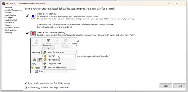
Starting with SolidSteel parametric has never been easier, thanks to the new interactive Introductory Assistant. This built-in tutorial guides you through your initial designs, covering basic working methods, handling profiles, components, and connections. No need to search for external resources—the Introductory Assistant offers a structured, step-by-step learning experience directly within the software, ensuring you can quickly become proficient in using SolidSteel parametric.
Drawing Assistant
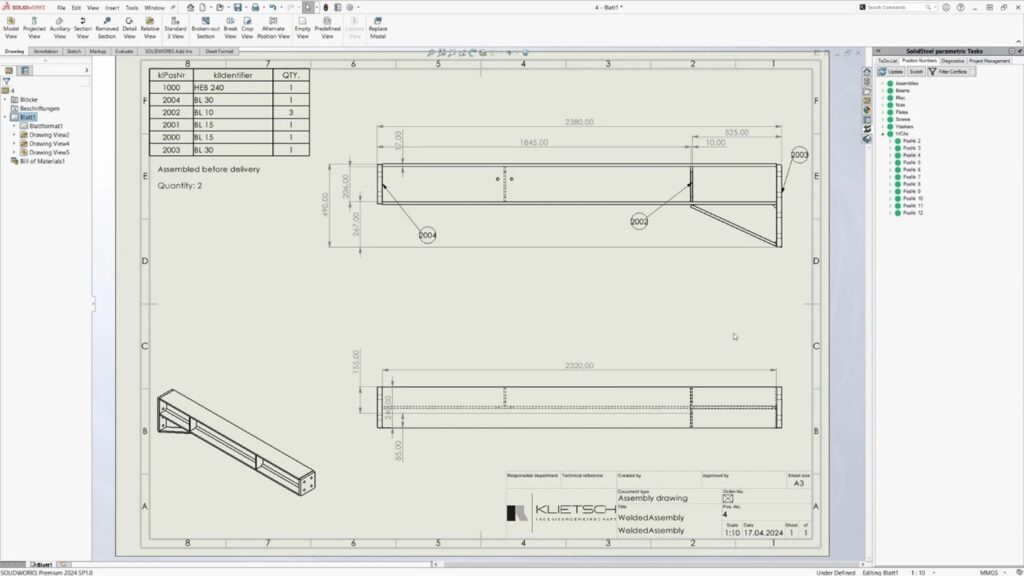
Recognizing the critical role of shop drawings in many companies, the new Drawing Assistant has been completely redesigned based on user feedback.
This feature now includes:
– Dedicated User Interface: Easily manage all parts, assemblies, and their status in relation to drawings. Decide whether to create new drawings, update existing ones, or not create drawings at all for each part.
– Automated Shop Drawings: Automatically generate shop drawings for all profiles, sheets, welded assemblies, and main/sub-assemblies created with SolidSteel parametric. This includes parts created with standard SOLIDWORKS functions, provided they follow the SolidSteel parametric part template.
– Individual Drawing Settings: Customize drawing templates for each part and assembly, allowing for different bill of material formats on assembly and welded assembly drawings.
– Update Function: Preserve all existing drawing information when parts are modified. Only the dimensions affected by the change are updated, saving you from redundant work during late design changes.
– BOMs on Drawings: Automatically include bills of materials on assembly and welded assembly drawings based on your drawing templates, eliminating manual rework.
– Dimensioning Options: Choose between chain dimensioning and ordinate dimensioning based on your project needs or company standards.
Enhanced Diagnostic and Management Tools
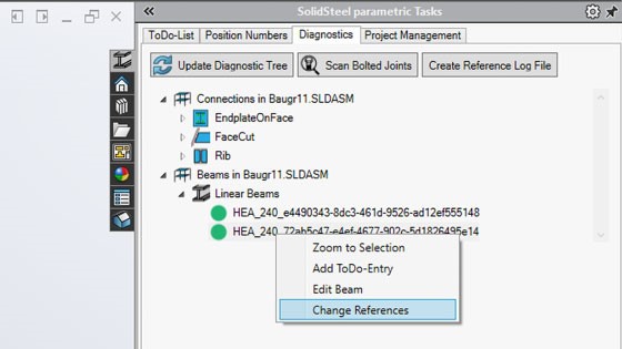
Diagnostics Tab
– View profiles, create ToDo entries, and edit profiles directly from the Diagnostics tab.
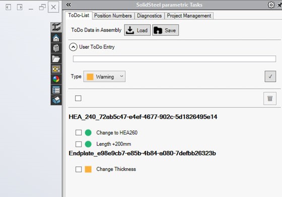
ToDo Manager
– Automatically load and update ToDos when opening an assembly.
– Temporarily store ToDos when switching between assemblies.
– Delete multiple entries simultaneously.
PDM Equal Part Detection
– The “Finalize” function has been renamed to “PDM Equal Part Detection”, for a bit more clarity.
– Post-detection changes on the assembly are blocked to ensure consistency.
SDNF Data and Profile Updates
– Detailed change tracking for SDNF files.
– Updated profile database with UK standards including CHS, SHS, and RHS as per EN 10210 and EN 10219, and flat, square, and round bars as per EN 10025-2.
Additional Improvements
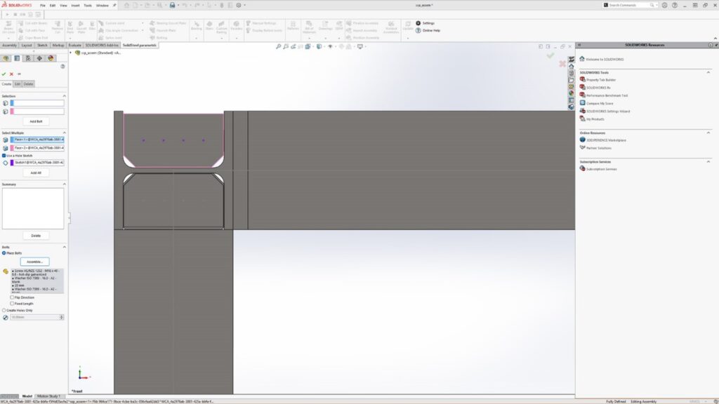
Manual Bolting
– Position holes and bolted connections using hole sketches for precise customization.
Miscellaneous and Bug Fixes
– Enhanced stability and error corrections across various functionalities, including SDNF import, diagnostics, railings, and connection management.
– Improved handling and editing of profiles, connections, and bolted joints.
Important Note: Password Update Required
To use the new version 6.0.0, you will need to request new passwords. You can conveniently request these through the Klietsch PasswordCenter or from your SolidXperts representative.
Conclusion
SolidSteel parametric for SOLIDWORKS version 6.0 is packed with powerful features and improvements to make your design process more efficient and intuitive. From the comprehensive Introductory Assistant to the robust Drawing Assistant and beyond, this update ensures you can achieve higher levels of automation and significant time savings in your daily work.
For more information or to request your new passwords, contact SolidXperts today and take your structural steel design to the next level with SolidSteel parametric 6.0.
What are the new features and updates in SOLIDWORKS?
SOLIDWORKS 2024 introduces enhancements like improved simulation capabilities, enhanced performance for large assemblies, and a streamlined user interface for better productivity. These updates aim to provide a more efficient and seamless 3D design experience for users.
Key Highlights
Improvements in core CAD functionality, simulation capabilities, and collaboration tools.
Improved performance, streamlined workflows, and enhanced customization options.
With each new release, SOLIDWORKS brings a range of new features and enhancements to improve the design experience and streamline workflows. This year’s release focuses on providing a seamless design experience and enabling users to work smarter, faster, and more efficiently. From enhanced performance and speed to advanced simulation features and cloud integration, we’ll uncover a goldmine of tools and functionalities to boost productivity and unleash creativity. So, let’s dive in and discover the latest features in SOLIDWORKS 2024!
From CAD to PDM: A Comprehensive Overview
With a focus on improving core CAD and Product Data Management (PDM) capabilities, SOLIDWORKS 2024 enhances the design experience and empowers users like us to create complex and innovative designs.
For example, as a core improvement on the list, there are more advanced tools for creating and managing complex assemblies. Easily define and manipulate assembly structures or organize and navigate larger projects. With these new functionalities you can create and manage your sub-assemblies, components, and in-context relationships much more efficiently. Also, you have access to enhanced sketching tools, which include the capability to generate intelligent, immediate sketch dimensions. This feature simplifies the creation of intricate geometries. Take advantage of these new functionalities to craft your most elaborate designs, whether they involve sheet metal or plastic components!
Key Enhancements and Innovations
SOLIDWORKS 2024 adds a range of key innovations that enable you and your design teams to achieve better designs faster.
Enhanced capabilities in product development disciplines such as simulation, manufacturing, and data management.
Improved performance and speed to accelerate workflows and optimize productivity.
Streamlined design processes with new tools and functionalities for complex geometry and organic shapes.
Advanced simulation features for more accurate and efficient analyses.
These enhancements and innovations are designed to help you streamline your design processes, boost productivity, and craft higher-quality designs.
User Experience Improvements
The 2024 release includes several improvements to workflows, customization options, and overall usability. The software now provides more streamlined workflows, allowing everyone to get more done, more quickly, and with fewer steps. You can expect improved navigation, simplified processes, and a more intuitive, productivity boosting interface.
Additionally, SOLIDWORKS 2024 offers increased customization options, allowing users to further personalize their workspace to suit their preferences and working style. You can customize your toolbars, menus, and shortcuts, making it easier to access your own most-frequently used commands and functionalities.
TL:DR, expect a more intuitive and personalized design environment, empowering you to focus on creativity and your innovative design process.
A Deep Dive into Performance Upgrades
SOLIDWORKS 2024 brings significant performance upgrades aimed at enhancing speed, efficiency, and your overall user experience. The new release focuses on improving various aspects of performance, making the design process smoother and more efficient.
2024 offers optimized file management capabilities, allowing you to manage and access your design data without losing valuable time or brain power. And, with this year’s design performance upgrades you can expect faster load times and improved responsiveness.
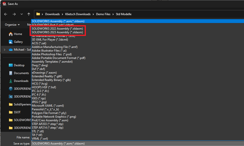
Backward Compatibility
It’s about time! SOLIDWORKS 2024 has officially introduced backward compatibility, letting you seamlessly work with projects created in SOLIDWORKS 2024, PLUS the previous 2 versions of the software.
You now have the power to open, edit, and save files from previous releases without any compatibility issues. Confidently collaborate on projects created in older versions of SOLIDWORKS, ensuring seamless integration and transition to the new release.
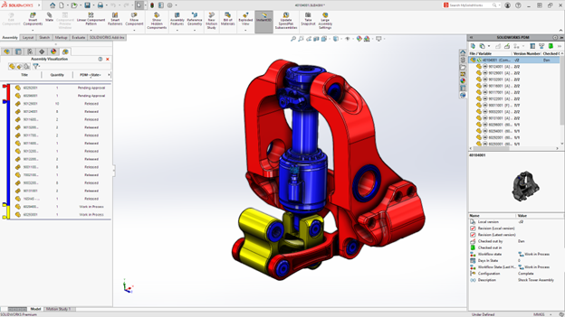
PDM Performance Improvements
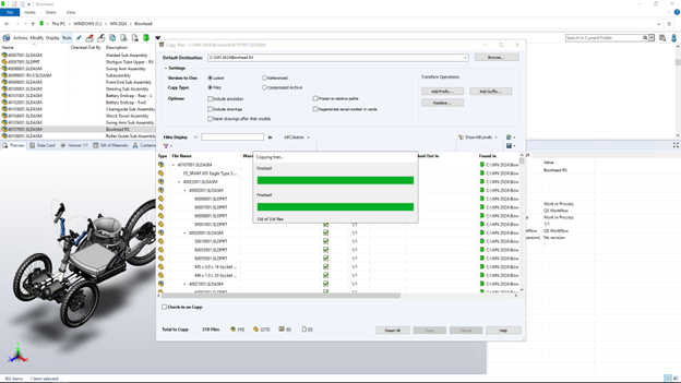
File-based operations are now twice as fast! Key operations such as adding files, changing state, and copying trees have seen significant speed enhancements.
View component data, including workflow states, directly within SOLIDWORKS using assembly visualization.
Enhanced web capabilities make it easier to access and manage data remotely.
Specific icons for weldment cut-list components simplify identification and streamline the design process.
Access system information in SOLIDWORKS via the Task Pane for convenient access to file versions and other critical data.
In version 2024, all these upgrades really smooth things out and make using SOLIDWORKS PDM a whole lot easier and faster for everyone.
Advanced Simulation Features for Enhanced Model-Based Design (MBD)
The 2024 release focuses on enhancing simulation capabilities, empowering you to optimize designs and make informed engineering decisions. Access more sophisticated analysis tools to perform complex simulations with ease, and conduct advanced structural analysis, thermal analysis, and fluid flow simulations to validate and optimize your designs before any prototyping even starts.
Additionally, SOLIDWORKS 2024 provides improved integration between design and simulation, enabling the seamless transfer of your data and analysis results. Streamline your workflows between design and simulation, making it easier for your engineers to iterate and refine their designs based on simulation results.
Enhanced Tools for Complex Geometry
Newly introduced advanced surfacing tools now allow you to create and edit complex surfaces more efficiently. Manipulate and control surfaces with precision, resulting in intricate and highly detailed designs. Additionally, SOLIDWORKS 2024 provides enhanced tools for creating sheet metal and plastic parts. With the enhanced tools for complex geometry in SOLIDWORKS 2024, you can push the boundaries of your designs to create intricate and innovative products.
Automation Features to Boost Productivity
SOLIDWORKS 2024 now offers automated processes for common design tasks, allowing you to complete them more quickly and with fewer manual steps. Automate tasks such as creating mates, dimensioning, and creating exploded views, saving valuable time and effort.
Additionally, SOLIDWORKS 2024 provides advanced automation capabilities for customizing design processes. You can more easily create macros, scripts, and custom functions to automate specific actions and repetitive tasks, further boosting productivity and efficiency.
Customization and Flexibility in SOLIDWORKS 2024
This year, gain a full toolbox of customization and flexibility options that allow you to personalize your workspace and adapt everything to your preferences. Customize toolbars, menus, and shortcuts, making it easier to access your frequently used commands and features.
Also, SOLIDWORKS 2024 adds flexibility to your design processes, allowing you to adapt the software to your specific workflows and requirements. Try out custom templates, standards, and design processes.
More Than Just Cloud Storage: Leveraging the 3DEXPERIENCE Platform
SOLIDWORKS 2024 alongside the 3DEXPERIENCE platform gives you access to a diverse kit of cloud-based tools to upgrade your designs and boost collaboration.
The 3DEXPERIENCE platform provides a comprehensive suite of applications and services that enable users to connect, collaborate, and innovate. You can seamlessly access the platform’s capabilities directly from their SOLIDWORKS environment. Tap into the power of the cloud for real-time collaboration, secure data storage, and advanced design capabilities to collaborate and create better designs, leveraging the platform’s file management processes.
A Preview of Cloud-Based Project Management Tools
SOLIDWORKS 2024 offers a range of cloud-based project management tools that enhance collaboration and streamline workflows. Gain access to cloud solutions that will enable you to manage projects, share files, and collaborate with team members effortlessly.
One of the key cloud-based project management tools on the 3DEXPERIENCE is Project Planner. This tool allows users to create, track, and manage project tasks, timelines, and milestones.
SOLIDWORKS 2024 offers cloud-based collaboration tools, such as real-time document sharing and markup. Easily share design files, review, and annotate them in real-time, and collaborate with team members across different locations.
Why upgrade to SOLIDWORKS 2024?
SOLIDWORKS 2024 brings a wave of innovation and efficiency for designers and engineers with enhanced performance, advanced simulation capabilities, and seamless cloud integration. Its focus on customization and flexibility empowers you to tailor your workspace and boost productivity with automation features and new capabilities. Improved and simplified compatibility and support for hardware and systems, along with backward compatibility, makes the transition smooth. Embrace the future of design, where collaboration, speed, and precision converge to set new standards in CAD software.
How Do I Start the Upgrade Process?
To upgrade to SOLIDWORKS 2024, drop us a line! Give our Xperts a call or send us an email and we’ll guide you, stress-free, through the upgrade process, including the activation and setup of the new release. We can even help backup all your important data before starting the upgrade process.
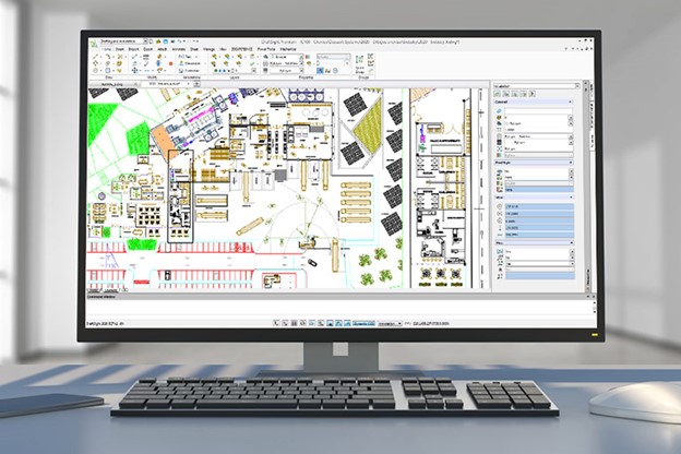
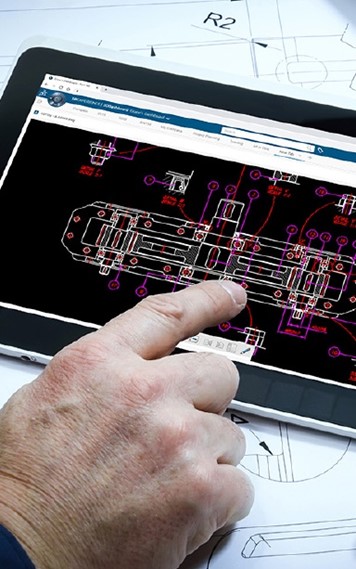
Understanding DraftSight for Advanced Product Design
DraftSight is a powerful CAD software that provides a comprehensive set of tools for creating, editing, viewing, and sharing 2D and 3D DWG files. It is designed for architects, engineers, designers, hobbyists, and professionals across various industries. Unleash your creativity and bring your ideas to life with precision and accuracy.
Key Highlights
Professional grade 2D CAD that allows users to create, edit, view, and markup 2D drawings and DWG files widely used in various industries such as architecture, engineering, construction, manufacturing, and design.
Easily integrated with SOLIDWORKS 3D CAD, allowing for seamless collaboration and management of DWG files.
Provides a familiar and easy-to-learn interface, making it accessible for beginners and experienced CAD users alike.
Introduction
Welcome to the world of DraftSight, a leading 2D drafting software from Dassault Systèmes, and a critical bridge between computer pixel and final physical product. We will delve into the basics, how to leverage it to streamline the journey from 2D drafting to 3D design, and how it can help bridge the gap between traditional drafting and modern product design and manufacturing. We’ll also provide tips and tricks for beginners to transition from traditional to digital drafting and explore advanced features that can enhance your workflow.
So, if you’re ready to take your drafting skills to the next level and unlock the full potential of CAD software, let’s go!
What is DraftSight and Who Needs It?
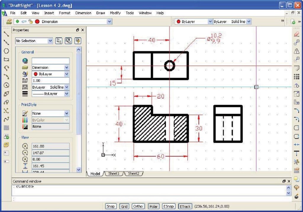
DraftSight is a professional grade 2D CAD software that offers a wide range of features and tools for creating, editing, and viewing 2D drawings and DWG files. It is an essential tool for architects, engineers, designers, and anyone involved in drafting or product design.
It provides a familiar and easy-to-learn interface, making it accessible for both beginners and experienced CAD users. Its intuitive interface and powerful capabilities make it your go-to choice for anyone in need of accurate and efficient drafting software.
From 2D Drafting to 3D Design
DraftSight has grown up along side the 3D industry, evolving from a 2D drafting tool to a full-fledged 3D design software, primed to help anyone move from traditional pencil-and-paper drafting to 3D technology. But how?
Versatility: All the necessary 2D drafting tools anyone could ask for, allowing users to create precise 2D drawings, with the added benefit of 3D design, enabling users to create complex 3D models.
Compatibility: Support for industry-standard file formats such as DWG, DXF, and DGN, ensuring seamless compatibility with other CAD software.
Automation: Tools that help speed up the design process, allowing users to automate repetitive tasks and improve productivity.
Collaboration: With DraftSight, users can easily share and manage design files, making collaboration with team members or clients a breeze.
Transitioning from Traditional to Digital: Tips and Tricks
Transitioning from traditional drafting methods to digital CAD software can be a daunting task, especially for beginners. However, with the right tips and tricks, you can make the transition smoother and more efficient.
Familiarize yourself with the interface: Take some time to explore the interface and familiarize yourself with its different tools and features.
Customize your interface: Customize the interface to suit your preferences. Take advantage of this feature to create a workspace that enhances your productivity.
Seek help from the community: If you have any questions or face challenges while using DraftSight, don’t hesitate to seek help from the DraftSight community. There are forums, user groups, and support channels available to assist you.
Integrating DraftSight into Your Current CAD Workflow
Integrating DraftSight into your current workflow is a seamless process that can enhance your productivity and efficiency.
Evaluate your current workflow: Assess your current workflow and identify areas where DraftSight can be incorporated to streamline your design process.
Import and convert existing files: The software supports various file formats, allowing you to import and convert existing design files into the new environment.
Collaborate with team members: Collaboration features make it easy to work on design projects with team members. Use the software’s sharing and markup tools to collaborate effectively.
Customize the interface: Personalize your interface to match your preferred workflow. Customize menus, toolbars, and shortcuts for quick access to frequently used commands.
Take advantage of automation tools: Automation tools can save you time and effort. Explore these tools and incorporate them into your workflow.
Overcoming Common Challenges for Beginners
Starting with a new CAD software can be challenging, especially for beginners. However, DraftSight is designed to be user-friendly and intuitive, making it easier for new users to overcome common challenges.
One of the main challenges for beginners is getting familiar with the interface and navigation. DraftSight’s interface is designed to resemble traditional drafting tools, making it easier for beginners to understand and use. Additionally, the software provides tooltips and on-screen guides to help you navigate and locate various tools and functions.
Another challenge for new users is understanding the different drawing and editing tools. DraftSight offers a comprehensive tutorial library that covers the basics of CAD drafting and design, including DraftSight basics. From creating basic shapes to advanced 3D modeling, the tutorials provide step-by-step instructions and practical examples to help beginners grasp the concepts and techniques.
DraftSight also provides a range of support options, including a community forum where users can ask questions and share their experiences. This creates a supportive and collaborative environment where beginners can seek guidance and learn from more experienced users.
With the right resources and support, beginners can quickly overcome the common challenges of learning DraftSight and start creating professional-quality products.
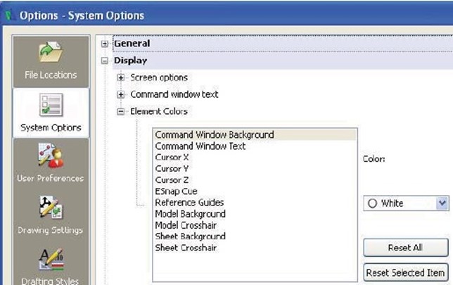
Setting Up for Success: Preparing Your Workspace in DraftSight
Setting up your workspace is essential for success in your design and drafting tasks. By customizing the interface to suit your preferences and needs, you can improve your workflow and efficiency.
Customize various aspects of the interface, such as the toolbar layout, command window position, and color scheme. By organizing the tools and commands you frequently use in a way that makes sense to you, you can access them more quickly and efficiently.
Additionally, you can create custom keyboard shortcuts and aliases for frequently used commands, further speeding up your workflow. These customization options make DraftSight a powerful tool that adapts to your working style and preferences.
By taking the time to set up your workspace, you can create a comfortable and efficient environment that allows you to focus on your designs and achieve the best results.
Using DraftSight for Collaborative Product Design
One of the key collaborative features of DraftSight is the ability to share and manage files. Easily share your designs with colleagues or clients, ensuring seamless collaboration and feedback. You can also control access rights and permissions, ensuring that only authorized individuals can make changes to the design.
Moreover, DraftSight enables multiple users to work on the same project simultaneously. This allows for real-time collaboration, where users can view and edit the design in real-time, improving communication and efficiency.
Sharing and Managing Design Files
DraftSight allows you to export your designs in various file formats, such as DWG, DXF, and PDF. This ensures compatibility with other CAD software and allows non-CAD users to view and review your designs. Additionally, options to customize export settings ensure that your design files are always optimized.
Version control and revision history features allow you to track changes and manage different versions of your design files. This ensures that everyone involved in the project is working with the latest version and reduces the risk of errors or conflicts.
DraftSight for Beginners: Team Projects
Utilizing DraftSight in team projects can greatly enhance collaboration and productivity. DraftSight offers features that enable multiple users to work on the same project simultaneously, making it an ideal tool for team-based design and drafting tasks.
Simultaneous usage: allows multiple users to access and work on the same design file simultaneously, enabling real-time collaboration and eliminating the need for manual file sharing and merging.
User permissions: options to control user permissions allow you to define who has access to specific design files and what actions they can perform.
Markup and commenting: allows users to add markups and comments to design files, facilitating communication and feedback within the team.
Revision control: version control and revision history features allow team members to track changes and manage different versions of the design file.
By utilizing these features, teams can collaborate seamlessly, improve communication, and achieve better design outcomes in their projects.
Simultaneous usage
User permissions
Markup and commenting
Layer management
Revision control
Enable multiple users to work on the same design file simultaneously
Control user access and actions on specific design files
Add markups and comments to facilitate communication and feedback
Organize and separate different components of the design
Track changes and manage different versions of the design file
Beyond the Basics: Advanced Features to Explore
While DraftSight provides a solid foundation for beginners, it also offers a range of advanced features that can take your skills to the next level. These features allow you to explore more complex techniques and enhance your productivity.
3D capabilities: powerful 3D modeling tools allow you to create and visualize complex 3D designs. You can create and edit 3D models, apply materials and textures, and generate realistic renderings.
Automation tools: automation tools, such as scripts and macros, can automate repetitive tasks and improve efficiency. By creating custom scripts, you can streamline your processes and save time.
Customization options: extensive customization options allow you to tailor the software to your specific needs and preferences. You can customize the interface, create custom commands, and define your own keyboard shortcuts.
By exploring these advanced features in DraftSight, you can unlock new possibilities in your routines and achieve more complex and sophisticated designs.
Automation Tools to Speed Up Things Up
DraftSight provides automation tools that can greatly improve your efficiency and productivity in design tasks. By automating repetitive tasks, you can save time and focus on more creative aspects.
One of the automation tools in DraftSight is the ability to create custom scripts and macros. These scripts allow you to automate repetitive tasks, such as batch processing, file conversions, and data extraction. By creating custom scripts, you can streamline your design process and automate time-consuming tasks.
DraftSight also offers a powerful scripting language, AutoLISP, which allows you to create custom commands and extend the functionality of the software. With AutoLISP, you can automate complex operations, create custom tools, and enhance your productivity.
By leveraging automation tools in DraftSight, you can speed up your design process, reduce errors, and focus on creating high-quality designs.
Conclusion
DraftSight is your ultimate companion for seamlessly transitioning from 2D to advanced 3D creations. Master the art of collaborative design, streamline your workflow, and unleash your creativity with its array of features. From customizing interfaces for efficiency to exploring automation tools, it empowers you to elevate your design game. Ready to bridge the gap between pixel and product? Dive into the world of digital design and bring your imaginative projects to life with ease.
Can DraftSight Help Bridge the Gap Between Traditional Drafting and 3D Design?
Yes, DraftSight can help bridge the gap between traditional drafting and 3D design. With its intuitive interface and comprehensive set of tools, DraftSight allows users to easily transition from traditional drafting techniques to 3D, enabling a smooth transition and improved design capabilities.
Can DraftSight be used for both 2D and 3D drafting, and what are the differences in using it for each?
Yes, DraftSight can be used for both 2D and 3D drafting. The main difference lies in the tools and techniques used for each. In 2D drafting, you focus on creating precise 2D drawings, while in 3D drafting, you create and manipulate 3D models. DraftSight provides the necessary tools and functionality for both types of drafting.
Any questions? Need help? Ask one of our experts.
Whether you’re ready to get started or just have a few more questions, you can contact us toll-free:
What products does Markforged offer in the 3D printing industry?
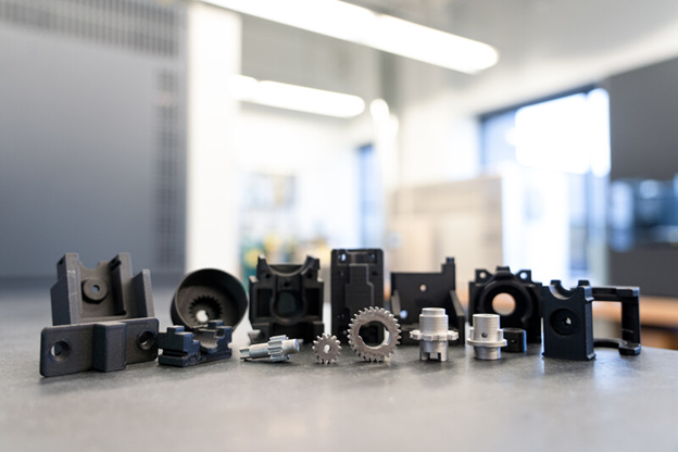
Markforged offers a wide range of 3D printers, including desktop and industrial models. Their products are known for their ability to print with industrial-strength materials like carbon fiber, Kevlar, and fiberglass, making them ideal for producing strong and durable parts for various applications.
Key Highlights
Revolutionizing the manufacturing industry with strong and durable parts.
Markforged printers have core features that make them stand out from other 3D printers in terms of precision, versatility, and durability.
The printing process with Markforged printers is easy and efficient.
Post-processing techniques such as cleaning and finishing are simple for optimizing prints.
Carbon fiber 3D printing finds applications in various industries such as aerospace, defense, automotive, and industrial manufacturing.
Introduction
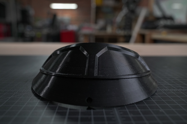
Markforged desktop 3D printers combine the benefits of additive manufacturing and carbon fiber material to produce functional and high-quality parts. Whether you are in the aerospace industry, automotive sector, or industrial manufacturing, Markforged printers can meet your needs.
In this blog, we will explore the world of carbon fiber 3D printing with Markforged. We will delve into the basics of carbon fiber material, understand its benefits in 3D printing, and explore the core features of Markforged printers. We will also discuss the design considerations for printing, the printing process with Markforged, post-processing techniques, common challenges, and advanced techniques in carbon fiber 3D printing. Let’s get started!
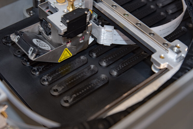
Understanding Carbon Fiber in Fused Deposition Modelling (FDM)
Markforged carbon fiber 3D printing combines the power of fused deposition modelling (FDM) technology, also referred to as fused filament fabrication (FFF), with the strength and versatility of carbon fiber, enabling rapid prototyping, complex geometries, and unparalleled customization.
The layer-by-layer approach of FDM 3D printing can create intricate geometries previously impossible or difficult to achieve with traditional methods and internal structures that can enhance the functionality of your printed parts while minimizing material usage.
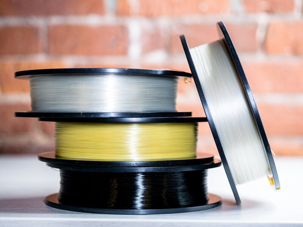
Markforged offers carbon fiber to your 3D prints in 2 ways: a polymer printing filament, Onyx, and as a continuous fiber inlay. Onyx is a micro carbon fiber infused nylon boasting high strength, durability, and resistance to chemicals. We’ll cover continuous inlays a bit later in our exploration.
The Basics of Carbon Fiber Material
Carbon fiber is widely used across industries thanks to its exceptional mechanical properties. It is composed of thin strands of carbon atoms bound together in a matrix material, resulting in a material that is stiff, strong, and lightweight.
One of the key advantages of carbon fiber is its high strength-to-weight ratio. It is stronger than many metals while being significantly lighter. This makes it an ideal material for applications where weight reduction is crucial, such as aerospace or automotive.
Carbon fiber also has excellent fatigue resistance, meaning it can withstand repeated loading and unloading without experiencing significant degradation in performance. This property makes it suitable for applications that involve cyclic loading, such as structural components in aircraft or high-performance sports equipment.
In addition to its mechanical properties, this material is highly resistant to corrosion, which makes it suitable for use in harsh environments or applications where exposure to chemicals is a concern.
From Prototypes to End-Use Parts: Benefits of Using Carbon Fiber in 3D Printing
Carbon fiber is an advanced material that offers exceptional strength, lightweight properties, fatigue and corrosion resistance. These properties make it an excellent choice for applications in industries that require high performance.
The printing process is more efficient compared to traditional manufacturing methods. You can create functional parts directly from digital files, eliminating the need for costly molds or tooling. This not only saves time but also significantly reduces your cost of production.
Additionally, traditional manufacturing methods often result in significant material waste, due to the subtractive nature of the processes. 3D printing adds material only where you need it, minimizing waste and making it a more sustainable manufacturing solution.
Overall, using carbon fiber in 3D printing allows you to create functional parts with more complex designs at a lower cost and with less material waste.
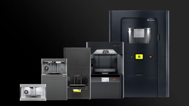
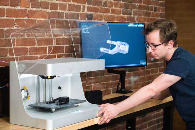
Introduction to Markforged Desktop 3D Printers
Markforged desktop printers are known for their precision, versatility, and durability. They are designed to deliver consistent and accurate prints, ensuring the highest level of quality. Whether you need to create functional prototypes or end-use parts, Markforged printers have got you covered.
Core Features of Markforged Printers
Precision: Markforged printers are designed to deliver high precision and accuracy, ensuring that every print meets the desired specifications.
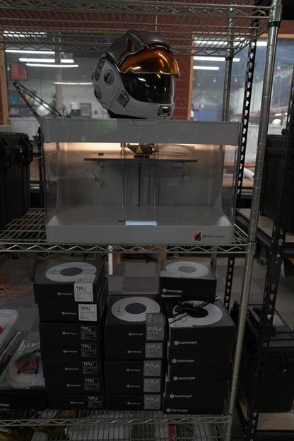
Desktop Size: Markforged desktop printers are compact and convenient for small-scale manufacturing or prototyping operations where space is a constraint.
Versatility: Markforged printers offer versatility in range of compatible materials. From nylon to patented continuous fiber reinforcement, these printers can handle a wide variety of materials, allowing for greater flexibility in design and application.
Durability: Markforged printers are built to withstand the demands of industrial use. They are durable and reliable, ensuring consistent performance even in high-volume production environments.
Comparing Markforged with Other 3D Printers
Deposition Technology: Markforged printers use a precise deposition technology that allows for the controlled placement of material, resulting in high-quality prints with excellent dimensional accuracy and surface finish.
Repeatability: Markforged printers are known for their repeatability, meaning that they can consistently reproduce the same results with each print. This is important for achieving consistent part quality and performance.
Range of Materials: Markforged printers offer a wide range of materials to choose from, including carbon fiber, nylon, and other polymers. This allows for greater flexibility in design and application, catering to a variety of industry needs.
Agility: Markforged printers are equipped with Eiger software, which provides a user-friendly interface and advanced features for optimizing prints. The software allows for easy file preparation, design optimization, and print management, enhancing the overall printing experience.
Overall, Markforged printers stand out from other 3D printers in terms of their deposition technology, repeatability, range of materials, and software agility. These factors make them a preferred choice for high-quality prints and versatile printing capabilities.
Preparing Your Design for Printing
When preparing your design for printing, consider the intricacies of additive manufacturing and the unique properties of carbon fiber. Take into account factors like dimensional stability, precise geometries, and the strength required for functional parts.
Take advantage of the software tools available in Eiger to optimize your design for the printing process, ensuring that your final product meets the desired mechanical properties.
Design Considerations for Additive Manufacturing
When designing for carbon fiber 3D printing, consider structural requirements, layer orientation, and part orientation to optimize strength. Utilize lattice structures for lightweight yet robust designs and ensure proper support structures for complex geometries. Factor in material properties like dimensional stability and mechanical strength for functional parts. Prioritize design for additive manufacturing to leverage the benefits of carbon fiber, such as durability and agility in production.
Software Tools for Optimizing 3D Designs
Eiger by Markforged offers features that optimize designs for additive manufacturing. Tweak parameters for print quality, material properties, and structural integrity. By simulating the printing process virtually, you can ensure that your designs will translate perfectly into physical objects.
Leveraging such software streamlines the manufacturing process, leading to efficient production of durable and precise parts.
Step-by-Step Guide to Your First Carbon Fiber Print
Let’s take a look at the printing process. Step one is always to ensure your Markforged printer is calibrated and that enough of the right filament is loaded.
Next, open Eiger and import your design. Select the material that best meets your application and adjust print settings to your liking. Generate toolpaths and preview the print.
If all looks good, send the file to the printer directly from Eiger.
Monitor your print’s progress either at the printer or online through Eiger. Once complete, carefully remove the print from the print bed.
Post-process by removing any support structures and gently sanding away any material left behind for a flawless surface finish.
Finally, celebrate your successful debut into carbon fiber 3D printing!
Tips for Ensuring Print Quality and Strength
To guarantee optimal print quality and strength when using your Markforged for carbon fiber 3D printing, consider these essential tips:
Ensure proper bed leveling and nozzle calibration for precise prints.
Optimize print settings such as layer height and infill density to balance strength and print time.
Monitor the printing process regularly to catch any issues early, and post-cure parts when necessary for enhanced strength and durability.
Post-Processing of Carbon Fiber Prints
Cleaning and finishing carbon fiber prints is a breeze. Finishing touches like sanding or polishing can further refine the surface quality. However, to enhance the final aesthetics and durability, use gentle cleaning methods to avoid damaging any intricate details.
Cleaning and Finishing Techniques
When it comes to cleaning and finishing techniques for your carbon fiber prints, precision is key. Gently remove any support structures using tools like pliers or tweezers. To smooth out rough edges, use fine grit sandpaper for a flawless finish.
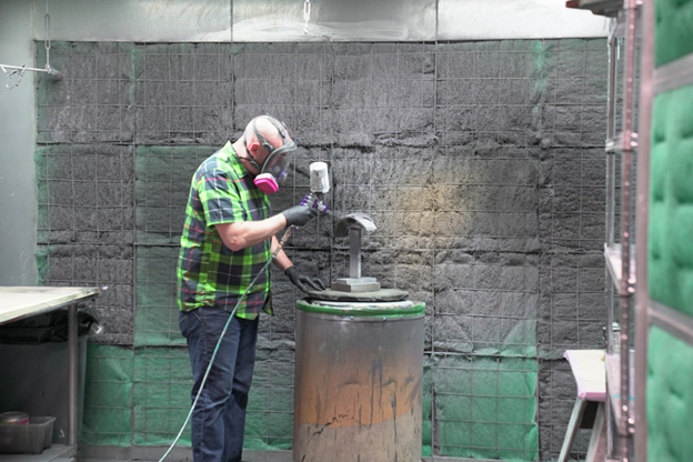
Post-Processing Safety Tips
Remember to prioritize safety when post-processing your prints. Wear appropriate protective gear like gloves and eyewear to avoid contact with any residual fibers or dust. Always follow the manufacturer’s guidelines for handling any finishing agents or solvents to prevent any accidents or health risks.
Remember, safety first!
Common Challenges and Solutions
Issues like delamination, warping, or filament breakage can occur. To combat this, ensure proper bed adhesion and environmental control. Fine-tuning print settings for layer adhesion and infill density can enhance strength. Also, inconsistent fiber alignment may lead to weaker parts; adjusting parameters in the slicer software can resolve this.
Regular maintenance, like calibrating and cleaning your printer, also plays a key role in mitigating challenges; Troubleshooting promptly ensures smooth printing processes and a long life for your printer.
Troubleshooting Common Issues
Regular maintenance and adjustment can resolve many printing problems, ensuring smooth and successful prints.
One common issue in FDM 3D printing is delamination, where layers separate. To address this, ensure the print bed is leveled correctly and your printer environment isn’t too humid.
Warping can occur due to inadequate bed adhesion or cooling, so adjust printer settings or environmental factors like temperature and humidity to prevent this.
Issues with layer adhesion might stem from incorrect print temperatures or inadequate filament flow. Check these settings and calibrate them for optimal results.
Advanced Techniques in 3D Printing
Advanced techniques elevate the capabilities of the material, offering unparalleled versatility and strength for various industrial applications. To enhance the strength of your carbon fiber 3D prints, try incorporating continuous fiber inlays.
Incorporating Continuous Fiber for Added Strength
This process involves strategically placing continuous strengthening fibers within your print to reinforce specific areas, providing added durability and structural integrity. By utilizing this method, you can boost the mechanical properties of your carbon fiber parts, making them ideal for applications requiring high strength and precision. This technique elevates the overall performance of your printed components, making them more resilient to various stresses and strains, contributing to the durability and functionality of your final product.
Applications for Carbon Fiber 3D Printing
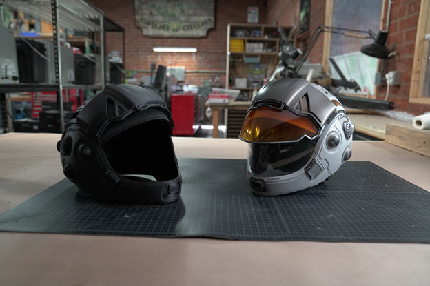
Aerospace and Defense, Automotive and Transportation, and Industrial Manufacturing are prime examples of where carbon fiber 3D printing excels. In Aerospace, the lightweight yet durable nature of the Markforged material enhances fuel efficiency. The Automotive sector benefits from the material’s strength to weight ratio for components like body panels. Industrial Manufacturing leverages carbon fiber’s durability for machinery parts.
These applications showcase the versatility and strength of carbon fiber.
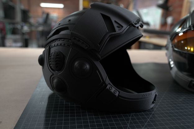
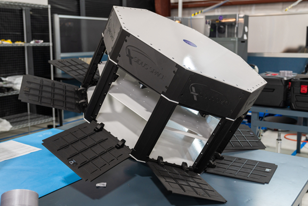
Aerospace and Defense
The lightweight yet sturdy nature of carbon fiber is ideal for creating parts with high mechanical properties and dimensional stability. Markforged’s printers can produce intricate designs with thin walls and complex geometries, ensuring precision and durability in critical components. By utilizing additive manufacturing technology, the production process is agile and cost-effective, making it a preferred choice for rapid prototyping and spare parts manufacturing in the aerospace and defense sectors, ultimately speeding up the product development process.
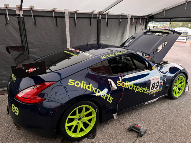
Automotive and Transportation
3D printing with carbon fiber has found remarkable utility in the automotive and transportation sectors. Markforged printers offer precision and agility in producing functional parts with superior mechanical properties. By incorporating continuous fiber, these printers create durable components ideal for applications requiring strength and lightweight characteristics. From rapid prototyping to spare parts production, Markforged drives innovation in automotive manufacturing.
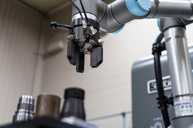
Industrial 3D Printing & Manufacturing
With its agility and versatility, Markforged brings additive manufacturing to the forefront of creating durable and functional parts for industrial applications. The precision and repeatability of Markforged printers ensure that complex designs with thin walls can be printed with utmost dimensional stability, meeting the stringent requirements of the manufacturing sector. Additionally, Markforged offers the unique capability of printing with composites through fused filament fabrication (FFF) for even stronger and more lightweight parts to be produced in a fraction of the lead time compared to traditional methods.
Transitioning to 3D workflows with SOLIDWORKS Pro enhances product design accuracy, facilitates efficient collaboration through shared models, and provides realistic visualization from all angles. It streamlines your processes with advanced tools for not only CAD, but sheet metal modeling, CAM integration, reverse engineering and more, saving time and boosting productivity. Kick your boring 2D routines to the curb and unlock the full potential of your designs, elevating your product development process to the next level.
Key Highlights
SOLIDWORKS Pro offers a seamless transition from 2D to 3D, enhancing the product development process.
Transitioning to 3D offers benefits such as improved product design, efficient collaboration, and enhanced visualization.
Key features like advanced modeling tools, sheet metal capabilities, and CAM integration.
Integrating SOLIDWORKS Pro into your workflow offers additional benefits like powerful simulation, realistic visualization, and streamlined documentation.
Getting Started in 3D with SOLIDWORKS Pro
Congratulations on taking the first steps towards transitioning from 2D to 3D design! It all starts with a SOLIDWORKS Professional license and a dream. This shift opens up a world of possibilities, offering enhanced product design, efficient collaboration, and advanced visualization. As we delve into the possibilities, you will discover a full range of features designed to streamline your workflow, save time, and boost productivity.
Integrating SOLIDWORKS Pro into your process will revolutionize the way you approach product development. By harnessing the power of shared 3D models and realistic visualization, this software empowers you to elevate your designs from every angle. With advanced tools for CAD, sheet metal modeling, CAM integration, and more, including the file management capabilities of SOLIDWORKS PDM Standard, you can bid farewell to mundane 2D routines and embrace a new era of efficiency and creativity.
Key Features for 3D Modeling
SOLIDWORKS is robust 3D modeling software designed to help you create intricate designs. Its advanced tools enable smooth model creation and editing, including standard features such as sheet metal design, CAM integration, and stress analysis. The sheet metal features streamline the creation of sheet metal parts, encompassing flat patterns and bends. Integration with CAM simplifies machining processes, while built-in stress analysis tools verify structural integrity. With all the features of SOLIDWORKS Standard, Professional also includes additional features such as wizards to automate designs, perform stress analysis, and determine the environmental impact of components, making it the ultimate tool for seamless 2D to 3D transition with the added capability of SOLIDWORKS Simulation Standard.
Setting Up Your First 3D Project in SOLIDWORKS Professional
Let’s break down the process of setting up your first 3D project in SOLIDWORKS Pro step by step:
Create a New Part or Assembly File:
Open SOLIDWORKS Pro.
Choose “New” from the File menu.
Select either a part or assembly file, depending on your project requirements.
Try choosing standard templates to help you get started.
Define Your Project:
Give your project a descriptive name.
Set the units (e.g., millimeters, inches) for your design.
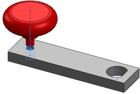
Sketch Your Design:
Use the sketch tools to create the basic shape of your 3D model.
Add dimensions and constraints to define the geometry.
Extrude or Revolve:
Extrude or revolve your 2D sketch to create a 3D solid.
Adjust the dimensions as needed.
Apply Features:
Use features like fillets, chamfers, and holes to enhance your design.
SOLIDWORKS Pro offers a wide range of tools for creating complex shapes.
Save Your Project:
Save your work frequently to avoid losing progress.
Start Designing!
With your project set up and tools at your disposal, unleash your creativity and start designing confidently.
Remember, SOLIDWORKS Pro provides a robust environment for 3D modeling, and by following these steps, you’ll be well on your way to giving your designs a full 3D overhaul!
Advanced Techniques in SOLIDWORKS CAD for Efficient Design
Once you’ve mastered the basics of SOLIDWORKS Pro, it’s time to delve into advanced techniques to enhance your design process.
SOLIDWORKS Pro offers a suite of advanced features tailored for efficiency. These include leveraging assemblies for complex designs, utilizing cut lists and cost estimation, and integrating composite materials. Additionally, SOLIDWORKS Pro provides tips for efficient sketching and 3D modeling, alongside utilizing SOLIDWORKS Premium and CAD integration capabilities. By mastering these techniques, you elevate your designs and optimize the product development process.
Leveraging SOLIDWORKS Assemblies for Complex Designs
In SOLIDWORKS Pro, using assemblies is a big help! With intelligent tools and features, they can give accurate cut lists, estimate costs, and handle materials like composites. With the cut list feature, you can know exactly how much material you need. Cost tools predict manufacturing expenses. Plus, it’s great for working with cool materials like carbon fiber or fiberglass. You can easily figure out shapes and sizes when they’re flattened.
Simply put, SOLIDWORKS Pro with its assemblies is like having a smart assistant for making complex designs and manufacturing simpler.
Tips for Efficient Sketching and Modeling in 3D
Designers have access to a range of tools and features that can enhance their sketching and modeling process. Here are some tips for efficient sketching and modeling in 3D using SOLIDWORKS Pro:
Utilize advanced sketching tools for precise and efficient sketch creation.
Leverage efficient design iterations and modifications.
Utilize the comprehensive library of prebuilt 3D CAD models and other CAD data available in Toolbox.
Integrating 3D into Your Workflows
Integrating SOLIDWORKS Pro ramps up your design game and boosts productivity. It’s packed with features that smooth out every design stage, from simulation to documentation.
You get stress analysis tools, stunning visualizations with Visualize, and top-notch documentation. Plus, there’s PDM for file management, automation to speed up tasks, and a toolbox for quick access to CAD models.
Collaborating on Projects
Collaboration is essential in any design project, and SOLIDWORKS Pro nails it with a variety of features. Whether you’re teaming up with engineers, electrical designers, or other stakeholders, it has tools to make collaboration seamless.
For electrical design, there’s CircuitWorks for ECAD/MCAD data sharing. Plus, there’s eDrawings Professional, making it a breeze to share 3D models and 2D drawings via email. With Pro’s collaboration features, including the ability to design and route electrical wiring, harnessing, cabling, and conduit assemblies in 3D, and the possibility to connect to the cloud-powered 3DEXPERIENCE platform, designers can boost communication, streamline workflows, and elevate the entire design process with additional capabilities for collaborating on projects.
Overcoming Common Challenges in Moving to 3D
Some common challenges in moving to 3D design include adapting to new software, transferring existing 2D or CAD data to the new system, and ensuring compatibility with other design tools and processes. To overcome these challenges, SOLIDWORKS Pro provides troubleshooting tools for typical issues, strategies for smooth transitioning, and comprehensive support for design engineers.
Strategies for Smooth Transitioning from 2D to 3D
Transitioning from 2D to 3D requires careful planning and execution to ensure a smooth transition. Here are some strategies for smooth transitioning from 2D to 3D:
Define clear goals and objectives for the transition: Clearly define what you want to achieve with the transition to 3D design and communicate these goals to your team.
Plan and prioritize: Create a roadmap for the transition process, including a timeline and milestones. Prioritize which projects will be transitioned first based on complexity and impact.
Provide training and support: Invest in training for your team to ensure they are familiar with the tools and features at their disposal. Provide ongoing support and resources to address any challenges or questions that may arise.
Utilize built-in tools: Take advantage of tools for data migration, compatibility checking, and performance optimization to ensure a smooth transition.
Introduction to Simulation
Simulation is vital for design and SOLIDWORKS Pro, with its compatible add-ins, nail it with a robust set of tools and features for your design environment.
Simulation Standard offers stress analysis, motion analysis, and more, letting designers test their creations in various scenarios. This helps spot problems early, saving time and money on physical prototypes. With simulation features, designers are empowered to make smarter decisions, fine-tune designs for safety and performance, and ensure top-notch results.
Applying Simulation to Validate Your Designs
Now that you have your simulation data, what do you do with it? Validating designs is key in the design process, and SOLIDWORKS Pro has that covered too! Its purpose-built tools ensure designs meet performance and safety standards.
By running simulations using Simulation Standard, you can analyze stress distribution, evaluate motion behavior, and assess other key factors that impact your design’s performance. Leveraging Simulation allows for informed decisions, reducing design flaws and optimizing performance and efficiency.
Leveraging Visualize for Realistic Renderings
Effective communication relies on visualizing designs. Visualize simplifies the creation of realistic renderings. Designers can effortlessly produce top-tier visual content, enhancing presentations and marketing materials with photorealistic images. Visualize boasts advanced rendering features, including dynamic lighting and realistic textures, which make designs truly stand out. By leveraging Visualize, designers can craft compelling visuals that breathe life into their creations, effectively conveying their vision to stakeholders. It’s a valuable asset for elevating presentations, marketing collateral, and design reviews, ensuring stakeholders grasp the essence of the design accurately.
Conclusion
Transitioning from 2D to 3D design with SOLIDWORKS Pro not only unlocks enhanced product development possibilities but also offers improved visualization, advanced simulations, streamlined workflows, and seamless collaboration. Mastering SOLIDWORKS Pro empowers efficient design creation, while overcoming challenges through troubleshooting and smooth transitioning strategies ensures success.
Frequently Asked Questions
What Are the Prerequisites for Transitioning to SOLIDWORKS?
To transition to 3D design, some prerequisites include a basic understanding of mechanical design principles, familiarity with CAD data management, and a clear understanding of the design process. Additionally, having access to SOLIDWORKS tools and resources is essential for a successful transition to 3D design.
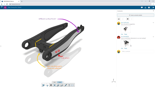
In our world of product design, efficient collaboration, and seamless lifecycle management are crucial. Thankfully, the 3DEXPERIENCE platform emerges as a powerful solution, offering a comprehensive suite of tools and applications designed to streamline the product development process. In this ultimate guide, we’ll delve into the intricacies of working with the 3DEXPERIENCE platform and explore the key features and functionalities of its associated apps.
Understanding the 3DEXPERIENCE Platform
At its core, the 3DEXPERIENCE platform serves as a business experience platform, providing robust product lifecycle management capabilities. This platform encourages and supports collaboration among your team members, allowing them to design products together, and guides them through the entire lifecycle from conception to final release.
Roles and Apps
Roles play a pivotal role in determining the apps and services accessible to you as a platform user. For mechanical designers working in collaborative teams, the Collaborative Designer for SOLIDWORKS role opens the gateway to a host of design routine-boosting functionalities.
With this role, users can:
Search for, store, and manage files in collaborative spaces on the 3DEXPERIENCE platform in the cloud.
Share files with team members and leverage product lifecycle management features such as lock and unlock, tags, and revisions.
Access additional apps and services in the 3DEXPERIENCE Marketplace.
The Collaborative Designer for SOLIDWORKS role comes with a set of apps that run within SOLIDWORKS and SOLIDWORKS Visualize, including:
Design with SOLIDWORKS
Render with SOLIDWORKS Visualize
Derived Format Converter (Optional)
*You’ll need both the 3DSwymer and Collaborative Industry Innovator roles before you can get started with Collaborative Designer.
Key Terms for Navigating the Platform
To effectively navigate the 3DEXPERIENCE platform and the 3DEXPERIENCE Connector for SOLIDWORKS, understanding key terms is essential:
Compass – The Compass serves as the gateway to the 3DEXPERIENCE platform, providing access to roles and apps.
Role – Roles define the scope of apps and services available to users, tailored to specific job requirements. Administrators can create custom roles for users.
Collaborative Spaces – Collaborative spaces are secure areas on the platform for storing and managing files, supporting version control, and enabling collaboration among team members.
Physical Product – A physical product is a configuration of a part or assembly that can be manufactured, each with a unique part number for efficient searching.
CAD Family and CAD Family Objects – CAD families encompass one or more configurations of a part or assembly. CAD family objects represent the root configuration, all saved in the same collaborative space.
Installing and Connecting
Installing the 3DEXPERIENCE apps requires several prerequisites, including platform credentials, a web browser, Java 11 JRE, SOLIDWORKS 2019 SP0 or later, and SOLIDWORKS Visualize Standard or Professional 2020 SP3 or later. Once installed, users can seamlessly connect to the platform and access the designated apps and services.
To install the 3DEXPERIENCE apps:
Close SOLIDWORKS and SOLIDWORKS Visualize.
Log in to the 3DEXPERIENCE platform.
If your company has an on-premises installation, contact your Administrator to get the sign-in link.
On the top bar of the 3DDashboard, click the Compass.
Under Me, click SOLIDWORKS.
6. Follow the prompts to download and install Design with SOLIDWORKS.
Creating Collaborative Spaces
Collaborative spaces are pivotal to the collaborative aspect of the platform. Users can create collaborative spaces to store, share, and manage files, providing a structured environment for efficient collaboration. Collaborative space owners and administrators have the authority to add members, assign access roles, and manage the collaborative space’s lifecycle.
Getting Started with 3DEXPERIENCE Apps
The 3DEXPERIENCE platform boasts a plethora of apps designed to cater to diverse needs. From project management to 3D model visualization, users can leverage these apps to enhance their workflow. The 3DDashboard serves as a portal, offering a centralized view of project and task information.
Commonly Used Apps:
3DSpace: Create collaborative spaces for data storage, sharing, and controlled access.
3DSwym: Connect with communities for collaborative discussions, questions, and information sharing.
3DSearch: Find content from various sources with the ability to filter results using 6WTags.
3DPlay: A viewer for manipulating 3D models, providing advanced functionalities such as sectioning, measuring, and annotating designs.
Managing Files in MySession
The MySession widget plays a pivotal role in managing your SOLIDWORKS on the 3DEXPERIENCE platform. Open, save, and export files seamlessly, utilizing the context menu or action bar. The FAQ section provides valuable insights into common queries related to saving all your SOLIDWORKS files, collaborative spaces, physical products, and CAD families.
The 3DEXPERIENCE platform, coupled with the Collaborative Designer for SOLIDWORKS role and associated apps, presents a comprehensive solution for modern product design and development. Whether you are a mechanical designer or a collaborative team member, this guide equips you with the knowledge to navigate the platform effectively, create collaborative spaces, and leverage the diverse range of apps available. Embrace the power of 3DEXPERIENCE for a seamless and collaborative product development experience.
It’s that time of year again, 3DEXPERIENCE World 2024 is quickly approaching, and our Xperts are beyond excited! Let’s embark on a journey of collaboration and creativity at 3DEXPERIENCE World 2024, where SOLIDWORKS users and Dassault Systèmes partners converge to explore the limitless possibilities of 3D design.
This event serves as an excellent platform for both SOLIDWORKS fans like you, and Dassault Systèmes partners like us, to come together in a shared space for networking, collaboration, and fresh inspiration. It provides a unique opportunity for everyone in our industry who shares a common passion for all things 3D to connect, exchange ideas, and build valuable professional relationships. Join us for an enriching experience February 11-14th in Dallas, TX where the whole SOLIDWORKS community can interact and explore the exciting possibilities within the realm of 3D design.
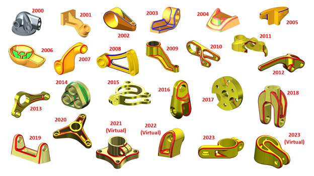
Model Mania – Where Design Magic Happens
Guess what’s turning 25 this year? It’s our favorite SOLIDWORKS modeling championship – Model Mania! This is the big 25th edition, and whether you’re a seasoned pro or a budding design enthusiast, you’re not going to want to miss this chance to be part of the action.
In-Person Excitement Returns to 3DEXPERIENCE World
After a few years of virtual high-fives due to the pandemic, 2023 brought back the joy of in-person interactions. And guess what? This year, 3DEXPERIENCE World is going all-in on in-person! That means you – yes, you – can dive into the excitement of Model Mania by being right there in Dallas.
How to Participate in the Model Mania SOLIDWORKS Challenge
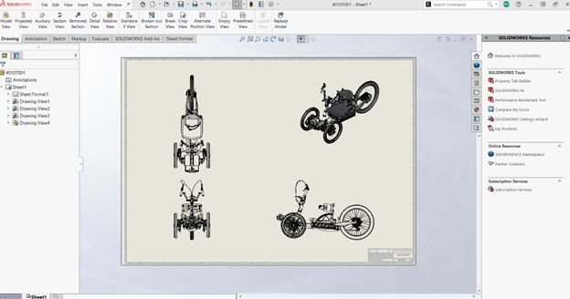
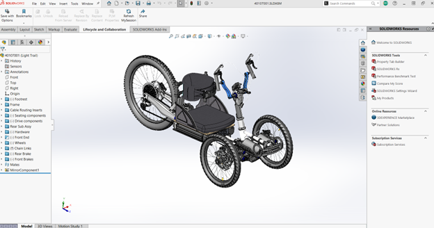
At 3DEXPERIENCE World, head over to the Model Mania booth in the Playground during the conference hours on Sunday, Monday, and Tuesday. This will be your chance to showcase your SOLIDWORKS skills and compete for 1st place.
But, what’s the challenge?
Six cubicles, each equipped with a desk, chair, and a laptop with the necessary software, await participants. First, you’ll receive a drawing of a part, Phase 1, and you’ll need to demonstrate your SOLIDWORKS Connected skills. Following successful completion of Phase 1, you’ll get a Phase 2 drawing, reflecting edits for the part.
The challenge, judged for accuracy and speed, promises an exciting experience for all. Winners will be announced at the Playground Theater on Wednesday, February 14th, at 12:30 PM CST, and the event will also be broadcast simultaneously on SOLIDWORKS Live!
Explore the 3DEXPERIENCE Hands-on Trial Zone
While at the Model Mania challenge, the Hands-on Trial Zone awaits your discovery. This interactive area is designed to give attendees an up-close and personal experience with the latest innovations in 3D design and collaboration.
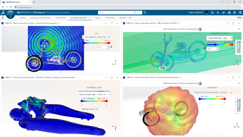
Dive into the cutting-edge features of 3DEXPERIENCE Works, including:
SOLIDWORKS + Cloud Services: Uncover the ease of sharing SOLIDWORKS designs through new Cloud Services included in every license. Experience the power of cloud collaboration from any location, on any device, all powered by the 3DEXPERIENCE platform.
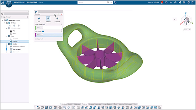
Next Generation Design: Engage in a hands-on exploration of next-generation design tools on the cloud, featuring freeform subdivision (SubD) modeling and browser-based CAD. This is where design possibilities meet practical application!
Simulation Showcase: Immerse yourself in a glimpse of the future with cloud-enabled simulation solutions for SOLIDWORKS users. Get hands-on with the newest and most advanced tools, powered by ABAQUS, and witness the potential of simulation-driven design.
While you’re at the 3DEXPERIENCE Hands-on Trial Zone, take advantage of the opportunity to test drive the latest technology, gain valuable insights, and engage in discussions with industry experts. It’s a collaborative space where you can explore, learn, and share your design experiences.
Spot the Xpert
As 3DEXPERIENCE World 2024 unfolds, keep your eyes peeled for the SolidXperience team – your go-to Xperts for all things 3D design! Whether you’re a seasoned SOLIDWORKS user, a Dassault Systèmes partner, or someone exploring the vast world of 3D innovation, we’re here to connect with you.
Feel free to strike up a conversation with any member of the SolidXperience group. We’re not just here to showcase our expertise; we’re eager to hear about your unique 3D design journey. Whether you have burning questions, exciting success stories, or are just curious to explore the possibilities, we’re all ears!
So, don’t be shy – Spot an Xpert, and let’s dive into the world of 3D design together.
Not registered for 3DEXPERIENCE World yet? Sign up today! Use code: 3DXW24Champ114 for 10% off at checkout.
Welcome to the SolidXperts guide on installing DraftSight Enterprise, a powerful 2D CAD software designed for large organizations. Tailored to enhance efficiency, this software offers a range of features, including network licensing, comprehensive technical support, and an intuitive interface. Our Xpert tutorial will walk you through the installation process, ensuring you unlock the full potential of DraftSight Enterprise for your team.
DraftSight Enterprise relies on the SolidNetWork license server to efficiently distribute licenses across users. To ensure smooth access for everyone within your network, this server software must be strategically installed on a centralized server or a machine that remains consistently connected.
If you’re ready to embark on the installation journey, this expert tutorial will guide you through the process, step by step. Without further ado, here is how to install Draftsight Enterprise. On the machine that will be used as the server, follow the following steps:
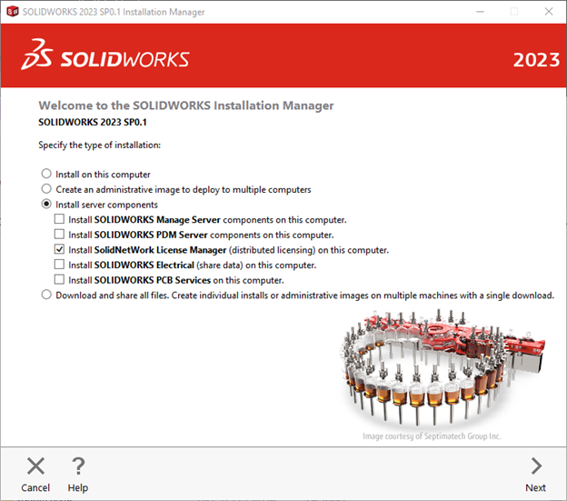
1 – First, download the SOLIDWORKS installation package and run setup.exe.
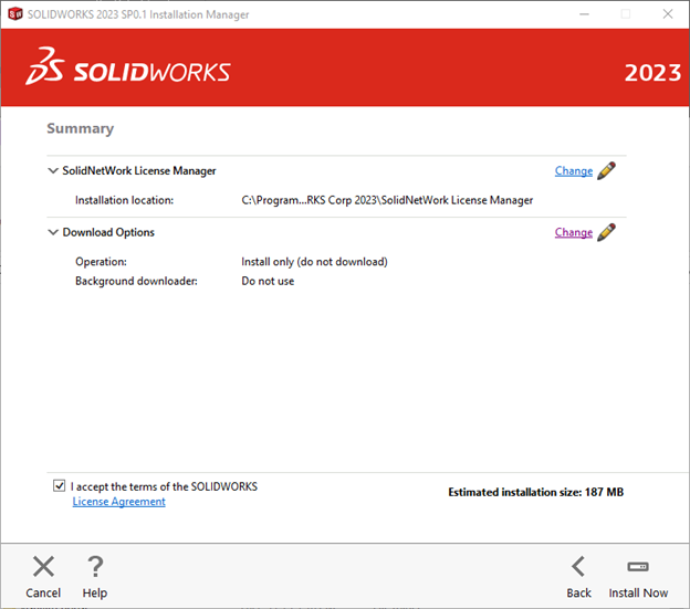
2 – Select “Install Server components” and “Install SOLIDNETWORK License Manager”. Click “Next”.
3 – On the next screen, after reviewing the License Agreement, select “I accept the terms of the SOLIDWORKS License Agreement”, and click “Install Now”.
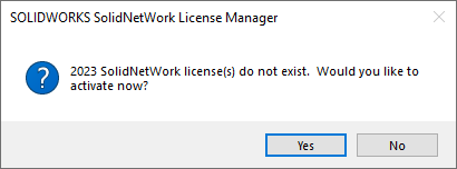
4 – Then once this is installed, from the start menu open:
SOLIDWORKS Tools 20xx à SolidNetWork License Manager server 20xx
In the following message box, click “Yes”.
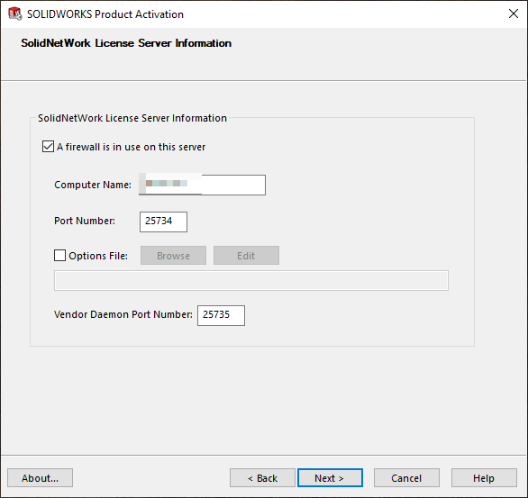
5 –Verify the SolidNetWork License Server Information, and click “Next”.
NOTE: Make sure firewalls are not blocking ports 25734 and 25735 on both ends of the connection.
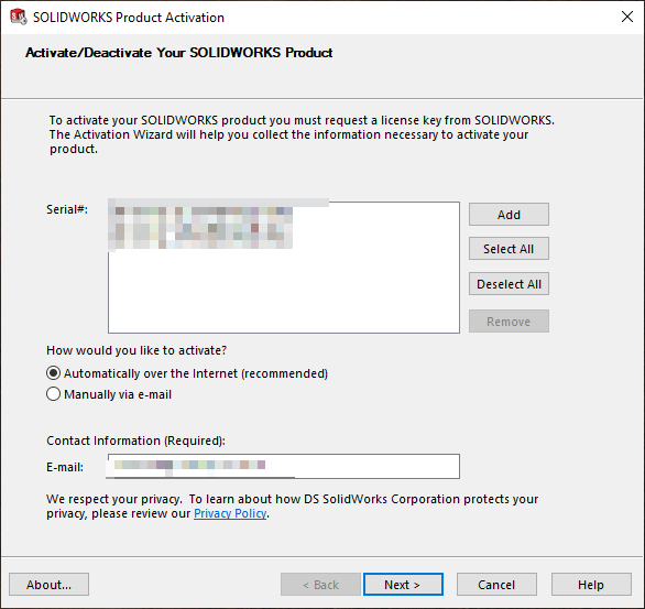
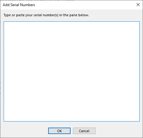
6 – In the following Product Activation window, on the right side of the white box, click “Add” to add a serial number.
7 – Copy & paste the serial number into the box. Click “Okay”.
8 – Then, put your email address in the box and make sure to check “Automatically over the Internet”. Click “Next”.
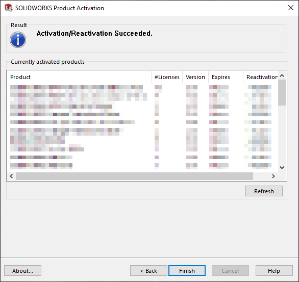
9 – The next window confirms your licenses from SOLIDWORKS. If everything looks good, click “Finish”.
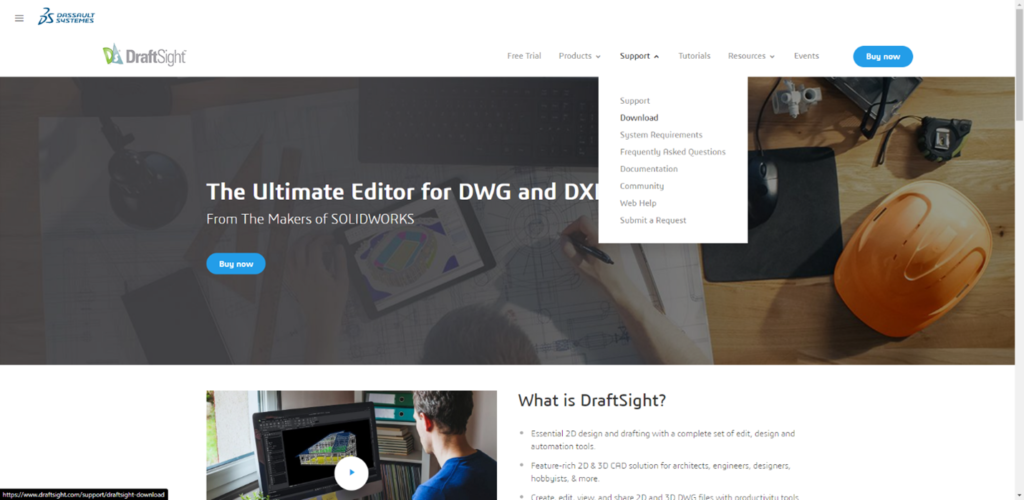
10 – Now is the time to install Draftsight on your workstations. Go to:
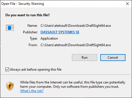
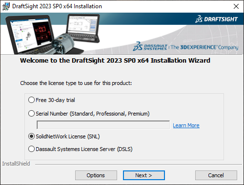
12 – Download and execute Draftsight.exe. Click “Run”.
13 – Choose SolidNetWorks License (SNL) and click “Next”.
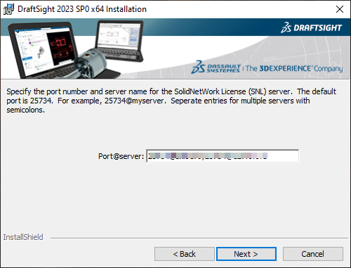
14 – In the box, provide the Port@Name of the server, inserting your server name or its IP address on the local server. Click “Next”.
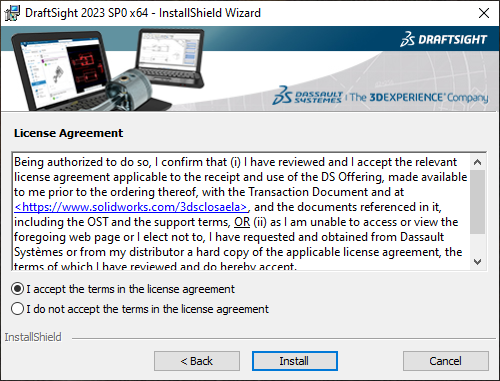
15 – Thoroughly review the agreement and check, “I accept the terms in the license agreement”, then click “Install”.
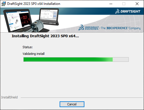
16 – Congratulations, you can now run DraftSight!
With DraftSight Enterprise successfully installed, your organization is perfectly positioned to leverage enhanced 2D productivity and collaboration. Don’t forget, SolidXperts is here to support your 3D journey every step of the way.
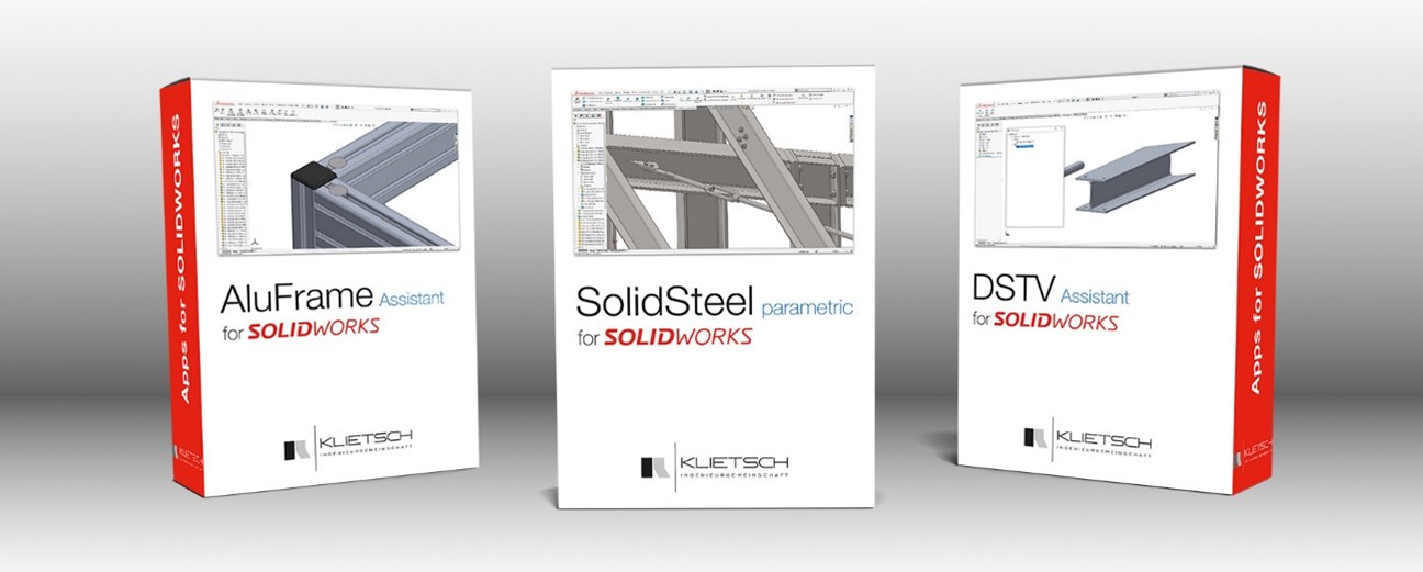
Montreal, Quebec – The SolidXperience Group, a leading provider of 3D engineering solutions in Canada and the United States, proudly announces a strategic partner withKlietsch, a distinguished German engineering firm and the developer of SolidSteel parametric. This collaboration seeks to support SolidXperience’s commitment to equipping the North American 3D design market with robust tools and comprehensive solutions. Effective January 1st, 2024, SolidXperience is the strategic partner of SolidSteel parametric in North America.
“As a Canadian with German ancestry, I’ve always had an affinity for German engineering and technology. Germany is known worldwide for having a strong engineering culture. So, forming a partnership with Klietsch, a German engineering company that developed a powerful SOLIDWORKS application, SolidSteel parametric, is a natural fit for my company. We look forward to building a strong partnership to advance this product in the North American marketplace,” says SolidXperience CEO and Founder, Alex Habrich.
Klietsch has a rich history of evolving to meet the needs of the engineering community. SolidXperience clients will benefit from Klietsch‘s extensive experience and the robust features of SolidSteel parametric, enhancing their SOLIDWORKS experience and streamlining their engineering workflows.
For more information or to learn how you can leverage SolidSteel parametric, or any of SolidXperience’s wide range of software and hardware, visit SolidXperts, or reach out directly to your SolidXperience Sales representative.
About SolidXperience:
SolidXperience is a leading provider of engineering solutions, dedicated to delivering advanced technology that empowers engineers and 3D designers. With a steadfast commitment to innovation and excellence, SolidXperience offers a range of products and services to enhance the full product development lifecycle, from ideation to manufacturing.
About Klietsch:
Klietsch is a Germany-based pioneer in engineering software, renowned for its flagship product, SolidSteel parametric. With a rich history and a commitment to technological excellence, Klietschcontinues to shape the future of engineering solutions globally.
Any questions? Need help? Ask one of our experts.
Whether you’re ready to get started or just have a few more questions, you can contact us toll-free:
Happy 2024 SOLIDWORKS enthusiasts🥳! Brace yourselves for a year brimming with boundless creativity, relentless innovation, and just a sprinkle of unconventional inventions. To embark on this exciting journey, let’s dive into the realm of SOLIDWORKS assembly modeling. As design complexity increases, mastering efficient assembly techniques becomes paramount.
To kick things off, we’ll share practical strategies to make your design process smoother and more efficient.
Component Organization
Start by establishing a structured approach to organizing your components. Utilize folders and sub-assemblies to categorize parts logically. This not only makes your assembly tree more manageable but also enhances collaboration when working in a team.
Top-Down Design
Explore the benefits of top-down design to create relationships between parts directly within the assembly. By defining key features and dimensions at the assembly level, you can ensure that changes propagate seamlessly throughout the entire design, saving time and reducing errors.
Efficient Mate Usage
Mates are powerful tools for establishing relationships between components. However, an overuse of mates can lead to performance issues. Opt for the smart use of standard mates and explore advanced mate options like width and symmetry to reduce the mate count and improve performance.
Simplified Configurations
Take advantage of configurations to manage different versions of your assembly. Create simplified configurations for specific purposes such as analysis, rendering, or lightweight viewing. This helps enhance performance during specific tasks without affecting the overall design.
SpeedPak
Integrate SpeedPak into your workflow to simplify assemblies even further. By creating a lightweight representation of your assembly, you can navigate and work with large designs more efficiently. This is particularly useful when dealing with intricate components and large assemblies.
Sub-Assembly Design
Break down your assembly into sub-assemblies based on functional or structural relationships. This modular approach makes it easier to focus on specific sections of your design, simplifies collaboration, and facilitates changes without affecting the entire assembly.
Component Patterns
Leverage component patterns to replicate parts efficiently. Whether using linear, circular, or sketch-driven patterns, this feature can save time and effort when dealing with multiple instances of the same component.
Assembly Visualization for Enhanced Assembly Insight
Take advantage of SOLIDWORKS Visualize to gain a deeper understanding of your assemblies. This powerful tool allows you to create stunning visual representations of your designs, providing invaluable insights. Use Visualize to analyze and optimize your assembly based on various parameters such as component size, mass, or custom properties. By harnessing the capabilities of SOLIDWORKS Visualize, you can identify and address potential performance bottlenecks while creating visually compelling representations of your designs. This tool not only enhances the efficiency of your assembly but also elevates your ability to communicate and showcase your work effectively.
By implementing these strategies, you can enhance your proficiency in SOLIDWORKS assembly modeling, leading to more efficient designs and improved collaboration within your team. Happy modeling!
Any questions? Need help? Ask one of our experts.
Whether you’re ready to get started or just have a few more questions, you can contact us toll-free:
Option 1: For licenses <1 year expired( Pay 2 Years Forward Upfront )
Get back on track with SOLIDWORKS CAD w/Cloud Services. By paying upfront for the next two years, you not only regain access to the powerful features of SOLIDWORKS but also enjoy cloud services to boost collaboration and efficiency.
Promotion Perks:
No need to worry about backdating and penalties. We’ll waive them for you!
Regain access to your design projects and continue where you left off, without any interruptions.
Option 2: For licenses >1 year expired ( Pay 3 Years Forward Upfront )
If your license has been expired for over a year, we understand the urgency to get back in the game. With this option, you can secure SOLIDWORKS CAD ALC w/Cloud Services.
Promotion Perks:
Our team is here to support your reintegration process, and we’ll waive backdating and penalties for a smooth transition.
Take advantage of the comprehensive SOLIDWORKS suite and unleash your creativity with the latest tools and features.
Option 1: Upgrade to 3DEXPERIENCE SOLIDWORKS
Seamlessly transition from SOLIDWORKS Desktop to 3DEXPERIENCE SOLIDWORKS, and experience a new dimension of design and collaboration. With secure cloud data management, increased collaboration capabilities, and reduced IT administration, 3DEXPERIENCE SOLIDWORKS empowers your team to work smarter and faster.
Option 2: Upgrade to SOLIDWORKS TERM w/Cloud Services
Opt for SOLIDWORKS TERM with Cloud Services, a flexible and convenient option that combines the power of SOLIDWORKS with the benefits of cloud-based solutions. Say goodbye to traditional licensing hassles and welcome easy deployment and automatic updates for a seamless design experience.
Promotion Perks:
This promotion covers both Standalone and Network licenses (SNL), making it suitable for businesses of all sizes.
Take advantage of the promotion price and add as many new licenses (3DEXPERIENCE SOLIDWORKS or SOLIDWORKS TERM w/Cloud Services) as you need on the same Purchase Order, with no limit on extra seats.
Enjoy the promotion discount for 3 years, whether purchased annually or upfront.
Even after the promotion period, you’ll continue to benefit with a 25% discount on successive years.