Christian Bagg, co-founder of Bowhead Corporation, is an admitted adrenaline junkie and outdoor enthusiast. After a snowboarding accident left him paralyzed from the waist down, all Bagg could think about was returning to his “normal” activities. His passion drove him to invent a mountain bike that accommodated the inability to use his legs. Although he was psyched to get back in the saddle again, another life-changing event lay just around the corner.
Bagg loaned one of his bikes to a camp for disabled children. There he witnessed a 14-year-old girl with cerebral palsy, who rarely spoke, return excited and energized from her first-ever experience of complete freedom on a bike. “Best day of my life!” she exclaimed. Her incredible joy galvanized Bagg’s mission: His company, Bowhead Corporation, would make access to mountain trails, woodland hikes, and the beauty of the great outdoors a reality for people around the world who have disabilities.
https://www.youtube.com/watch?v=88KPf6_Tq2A
Designs Evolve as Company Grows
With SOLIDWORKS 3D CAD, Bowhead Corp. introduced its innovative hybrid ATV/mountain bike a year ahead of schedule. Along with streamlining design efficiency, SOLIDWORKS Simulation enabled the Bowhead team to reduce its need for prototypes, which helped the company produce the bike with dramatically lower costs.
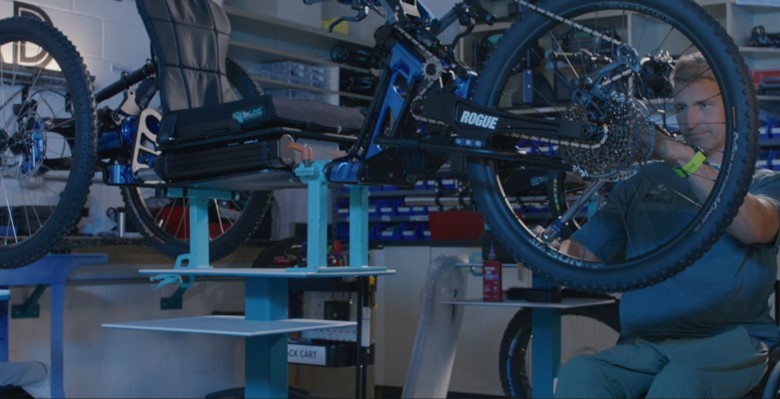
The first Bowhead Reach bike was delivered in November 2018. The company quickly learned that some riders were jumping over obstacles while sailing the bike up to eight feet in the air.

This prompted Bowhead to modify the base design by beefing up the shock absorber. It also replaced the throttle and braking controls with forearm paddles and built helmet-mounted bite throttles for use by quadriplegics.
“Now we have three bikes. We [also] have customer service, operations, engineering, and inventory management,” says Bagg. “SOLIDWORKS plays a role in every piece of our company.”
The growing company needed a data management and collaboration solution to continue working as an efficient and unified team.
Everyone on the Same Page
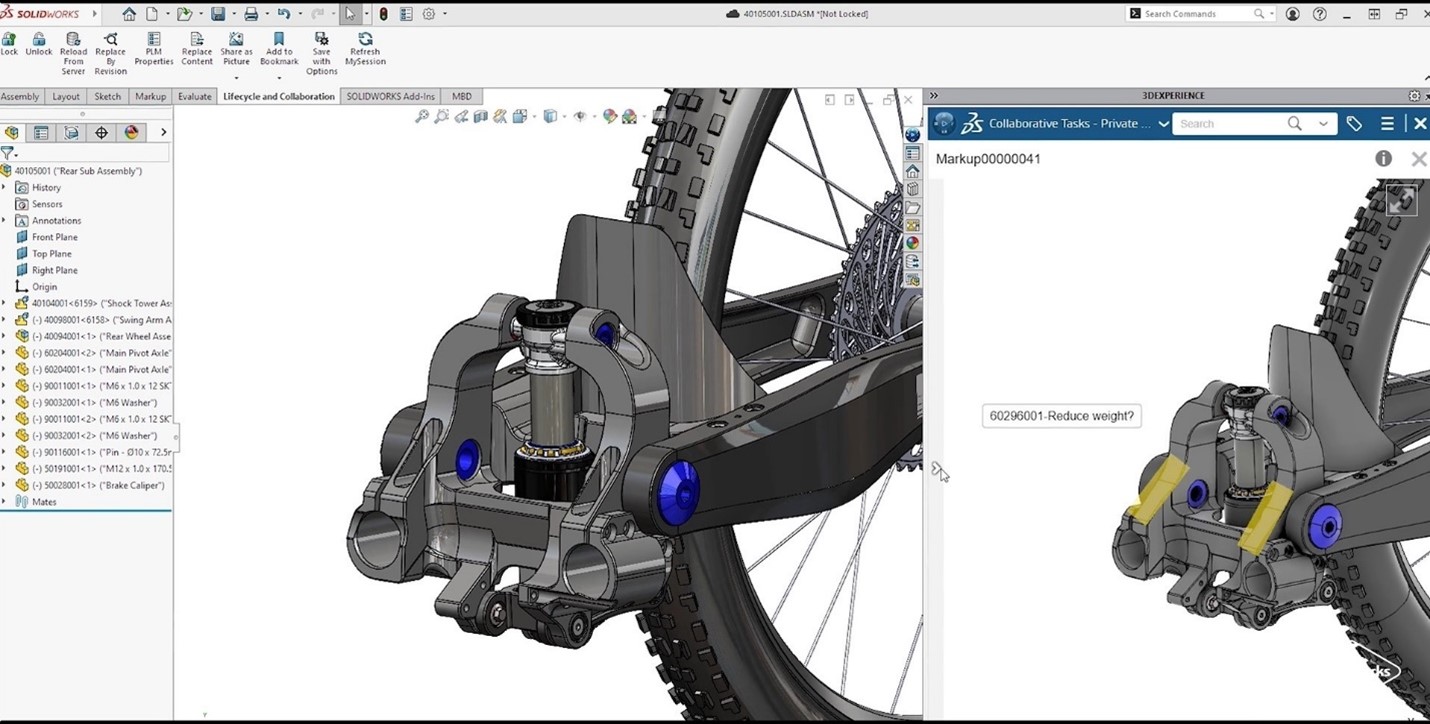
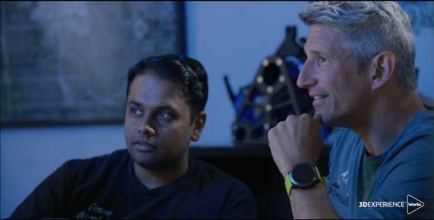
With 800 to 900 parts, Bowhead bikes are complex. “The [cloud-based] 3DEXPERIENCE platform became a way to manage an engineering company, not just to engineer the parts,” notes Bagg. “It was a funny moment realizing … that SOLIDWORKS and the 3DEXPERIENCE platform were more than just engineering tools,” he recalls. “They became this sort of marriage counselor between operations and customer service and engineering. It was a way for everyone to look at a problem in a focused manner and then deal with it as a team.”

Modifications during product development can originate from the shop floor, designers, managers, and even customers. “When you are working with a complex product like ours, it is very important that you stay on top of the changes,” says Mechanical Engineer Sanket Patil. “A simple change affects everything, be it in your assembly or processes.”
The browser-based aspect of the 3DEXPERIENCE platform brings familiarity to any user who accesses the internet. “One of the things that I really enjoyed was giving access to the platform to non-CAD users who needed access to it because they do so much with the data,” notes Patil. “I didn’t have to hold their hand [or teach them anything]. I sent them a link where they created their user credentials, and they started using the system like pros from day one.”
“You find different ways of using the tool that wouldn’t be obvious to an engineer. By using 3DEXPERIENCE, things become less obscure, and everyone starts speaking the same language. As a communication tool, we finally have one way to bring everybody together.”
-Christian Bagg, co-founder of Bowhead Corporation
Control As a Positive Force
Managing all product data, parts, inventory, and bills of material is critical for Bowhead’s operational efficiency, collaboration, and success.
VP of Engineering Roger McPherson notes, “… to maintain the quality of our product, control is really important. The 3DEXPERIENCE platform has been useful for us in that way. We must make sure that our changes—and they come from everywhere—are managed whether from builders, customers, quality, or suppliers. We must manage that [data in an automated way].”
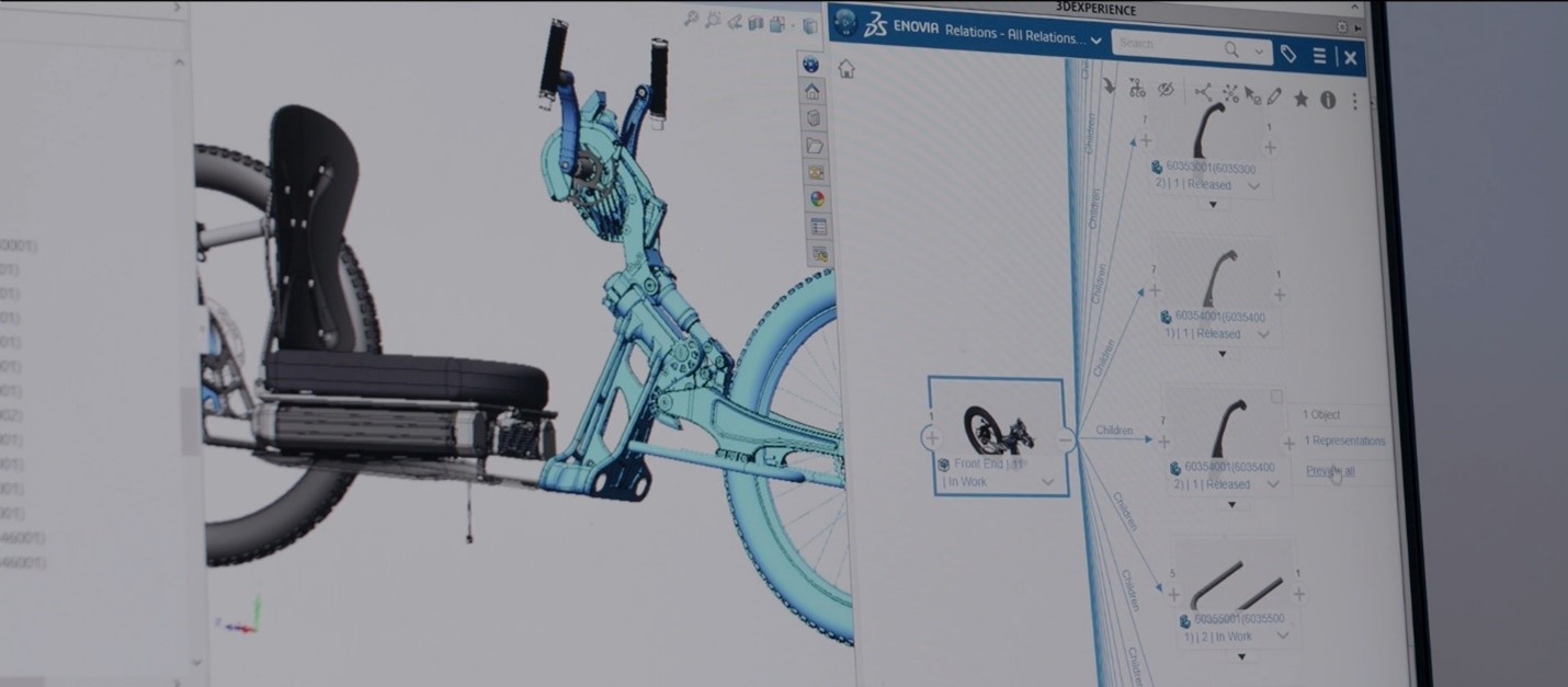
“All of our data is on the platform,” adds Patil. “We use the maturity states to control if a particular document or a part file or a drawing is being worked or if it’s released. This helps us to understand what is in the latest revision or what is the latest state of a drawing or a file.” Before using the 3DEXPERIENCE platform, Bowhead’s revision control was basically renaming a part file to something like “revision 1.11.2,” or “FINAL final revision.”
Great Communication Prevents Delays
Clear communication eliminates confusion and prevents duplicate or missed work, which improves productivity and speeds up the development process. When information is shared openly and effectively, all team members can make informed decisions faster and more effectively.
“As you grow your company, you really must grow the way you communicate. Having a cohesive, one-stop shop for communication has been, from a management side, the biggest addition of the 3DEXPERIENCE platform to the SOLIDWORKS engineering platform,” says Bagg.
For example, the company’s assembly team can now see inside the glass doors of an engineering room, so they feel like part of the engineering team. The 3DEXPERIENCE platform enables all key departments to give feedback on the design earlier in the process, which can help prevent misunderstandings and associated delays downstream.
Secure and Easy File Sharing
“We quite frequently share information (3D data and 2D drawings) with external stakeholders [via the 3DEXPERIENCE platform],” says Operations Specialist Tatiana Place. Some suppliers use the files to produce Bowhead parts. Others use 2D drawings to supplement the 3D model. Bowhead also sends files to a firm that supports the company’s engineering change processes when Bowhead’s in-house team needs additional help.
Place loves how the 3DEXPERIENCE platform has replaced cumbersome and confusing email communications and supports its collaboration with suppliers. “[The platform] has enabled us to amplify our workforce and continually innovate the rate that we come up with ideas,” concludes Place. “I can’t imagine a world without 3DEXPERIENCE right now.”
If you’d like more information about how the 3DEXPERIENCE platform can improve your data management, collaboration, and communication, contact our dedicated team of Xperts to learn how to make the platform part of your SOLIDWORKS workflow.

Any questions? Need help? Ask one of our experts.
Whether you’re ready to get started or just have a few more questions, you can contact us toll-free: